Add your feed to SetSticker.com! Promote your sites and attract more customers. It costs only 100 EUROS per YEAR.
Pleasant surprises on every page! Discover new articles, displayed randomly throughout the site. Interesting content, always a click away
RAH-66 Comanche, Torque Limiting Device 15 Jul 2013, 11:00 pm

Figure 1: RAH-66 Comanche
The Comanche RAH-66 reconnaissance and attack helicopter was developed by Boeing and Sikorsky for the US Army. The program entered engineering and manufacturing development (EMD) in June 2000, which required the construction of nine aircraft in addition to two prototypes. In an armed reconnaissance mission, Comanche could recognize and identify targets and digitally transmit the information to the battlefield commander in near real-time, select the optimum force deployment and coordinate the attack.
The airframe of the Comanche RAH-66 was crashworthy and ballistically tolerant to 23mm gunfire. The radar cross section was minimized primarily by the precisely shaped fuselage and internal weapons configuration. The helicopter had a composite five-blade bearingless main rotor and an enclosed composite fantail rotor for increased anti-torque capability. The rear rotor was able to withstand impact by 12.7mm rounds and provided a 180° turn in 4.7 seconds in hover mode and an 80kt snap-turn-to-target in 4.5 seconds.
The Comanche was equipped with a suite of passive sensors and a computer-aided Northrop Grumman mission planning system. This system carried out sensor data fusion, high-speed analysis and correlation of the sensor data. Northrop Grumman TASS (target acquisition system software) functions included automatic target tracking and target threat management. The analyzed data was presented to the crew in the cockpit displays or transmitted to other elements of the force, providing direct relay of near real time intelligence. Lockheed Martin Missiles and Fire Control developed the EOSS (electro-optics sensor system) which comprised: EOTADS (electro-optics target acquisition and designation system), including solid-state TV sensor, two-color laser rangefinder/designator, second-generation focal plane array long-wave FLIR (forward-looking infrared), and NVPS (night-vision pilotage system) with a second FLIR. The first complete EOSS system was delivered in June 2003.
Peregrine worked with Lockheed Martin Missiles and Fire Control systems on the Electro Optics Target Acquisition and Designation System (EOTADS). One of the key components that Peregrine assisted on was the torque limiting device to prevent damage to the EOTAD system when the direction of the system was driven too far to left or too far to the right. The torque-limiting device “Torque Tube” was designed from beryllium, 440c steel and stainless steel to provide an overall torque-limiting device. At the heart of the device, was a 3-D seat design that allowed for the device to separate where the torque limit was exceeded but the seat would remain intact within its operating range. If the EOTAD system was driven beyond its range the torque tube would prevent damage to the system by separating. Upon redirecting the EOTADS back into its operating range, the torque tube would reseat and operation of EOTADS would commence as specified. Due to the location of the device on the nose of the vehicle; weight, performance and the volume were constrained. Peregrine chose to design the torque tube from beryllium primarily for its stiffness and low weight qualities. As can be seen in Figures 4-6, two flanges exist on either end of the torque tube. There is a bellows that spans between the two flanges on either side. These bellows were diffusion bonded to the beryllium flanges. The torque tube then transferred its load through a beryllium shaft and into the seat. The seat is a complex 3-D arrangement requiring 5-axis machining. The seat was produced from 440c steel and was diffusion bonded to the beryllium shafts. Holding the overall torque tube together was accomplished by an internal spring load, creating a predetermined force across the seat for normal operation but allowing for separation if the instrument would hit a hard stop. As demonstrated in Figures 2 through 6, this device not only took engineering effort from the design of the seat and the transfer of the torque from one end of the device to the other, but also the use of exotic materials and exotic metal joining technology. Peregrine was successful in the overall production of the Torque Tube and the delivery of the units to Lockheed Martin for incorporation into the EOTADS system.

Figure 2: Torque Tube Model

Figure 3: Torque Tube in Cross Section

Figure 4: The details that make up a Torque Tube Assembly

Figure 5: Torque Tube ready for assembly (3-D seat shown)

Figure 6: The 3-D Seat
Peregrine is an aerospace and R&D product development company specializing in the design, simulation, fabrication and qualification of hardware for demanding applications.
Shunt Resistor Bank (SRB) Heater Plates for Satellite Application 15 Jul 2013, 10:30 pm
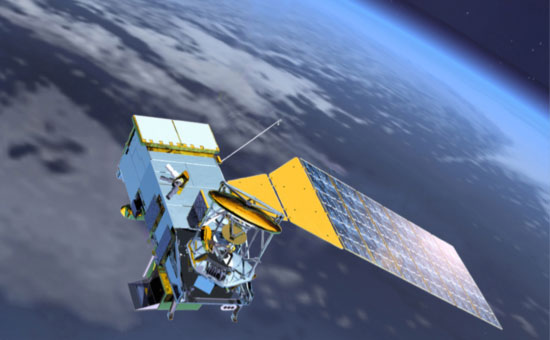
Figure 1: Thermal control device for a military satellite
Peregrine, in collaboration with its Aerospace customer, undertook a design, manufacture and testing contract to produce a set of shunt resistor bank heater plates for a satellite application. Specific to this application, is the requirement to dissipate 900 Watts of thermal energy into space. Due to the environment of space, this thermal load had to be transferred by radiation into space.
A morphological chart along with a Statement of Work was created between Peregrine and the customer for the design, manufacture and testing of these heater plates. Specifically voltages and amperage, along with envelope constraints were identified and parameters were established. Beginning from that point, Peregrine set off to establish a design that would allow the dissipation of the thermal energy and the creation of the overall model. Due to the constraints on volume, footprint and weight for satellite applications, Peregrine optimized the design to as small a footprint as possible. This was done by creating a set of serpentine cable heaters to be metallurgically joined to a carrier plate. In addition, an advanced thermal coating was applied in order to optimize emittance of thermal energy into space. The general radiation equation between two surfaces is typically derived as follows:
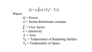
Based upon the above equation, Peregrine determined that four heater plates with a surface area of approximately 50 in2 each would be necessary in order to dissipate the 900 Watts of thermal energy. Peregrine modeled, analyzed and produced initial SRB plates in order to validate the design. Through the course of manufacturing, the cable heaters had to be precision formed, metallurgical joined to the carrier plate, and then the emittance surface was coated with thermal coating in order to achieve its proper finish. The cable heaters were terminated along one edge of the heater plate. At this location, lead wires were attached, the cable heater ends were glassed in order to seal against moisture contamination, housing was added and the final overall contact area was potted for strain relief. Each set of heater wires within the cable heater located on the SRB plate was electrically isolated from the plate. Each plate had the potential of dissipating 225 Watts of thermal energy. A bank of four plates equated to the 900 Watt goal.
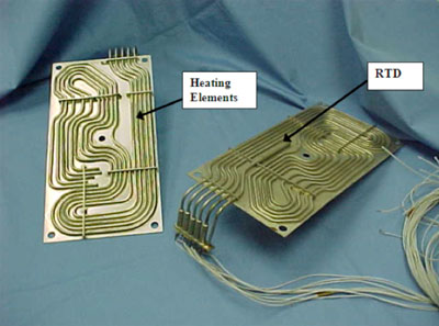
Figure 2: Shunt Resister Bank Heater Plate
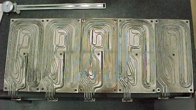
Figure 3: Fabricated Heater Plates in Process
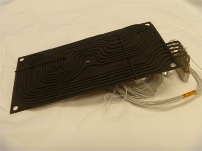
Figure 4: SRB Heater Plate with Thermal Coating for High Emittance
XMM Newton Satellite RGA Structure 15 Jul 2013, 10:00 pm

Figure 1: XMM Newton Satellite
The XMM Newton Satellite carries three telescopes to measure x-rays generated from extremely violent events from distant celestial objects. The XMM Satellite has been placed in a highly eccentric orbit reaching about one third of the distance to the moon, allowing the telescopes and detectors to operate unencumbered from the earth’s atmosphere with unprecedented sensitivity.

Figure 2: The beryllium RGA Integrating Structure with Reflection Gratings Shown; A Critical Component of the X-Ray Telescope
The XMM space borne observatory has been designed as a high through put x-ray spectrometer covering a broad band of energies. The heart of the payload consists of three telescopes developed under direct ESA contract by a consortium of firms. Each of the firms involved have a particular technical expertise for manufacturing specific parts of the telescope. The optics for each telescope consists of 202 nested grazing incident mirrors, or mirror modules, chosen to maximize the affected collecting area within the volume allocated.

Figure 3: XMM Telescope
Peregrine’s personnel were tasked with assisting in the design, analysis, fabrication and validation of the beryllium structures for the Reflection Grating Assembly. Beryllium is an advanced material which Peregrine has produced many critical structures from. These demanding applications have ranged from inertia guidance systems to primary satellite structures. Man-made materials have yet to surpass beryllium’s specific stiffness, stability and thermal properties.
Beryllium is a mature but exotic material. It has proven itself over time to be a reliable and high performance material. This is not to say that producing a product from beryllium is easy, but from the production of the raw materials to a finished product the processes have been defined and flight history exists to base a reliable design. Successful programs that apply their material typically form a strong tie between the analytical team and the product manufacturer.
Key Design Features of Beryllium
The inherent properties of beryllium that are ideally suited for spacecraft applications are:
- High Stiffness
- Stability
- Low Weight
Other properties of beryllium such as high thermal conductivity, moderate CTE, and high heat capacity are additional benefits to the material. Beryllium structures are typically high cost but their high performance and substantial weight savings more than offset the price.
Fracture toughness is a consideration when designing in beryllium materials. Beryllium’s fracture toughness (K1c) is 9 ksi per √in compared to aluminum’s 21 ksi √in. When designing with fracture sensitive materials, one must realize that the amount of stress that can be induced into a structure is limited by the flaw size that can be screened for and not necessarily the K1c value or yield strength.
The Integrating Structure is the main structural component of the Reflective Grating Array (RGA). It is a monolithic structure that supports the 202 reflection gratings of the RGA. This structure was required to be lightweight, possess high stiffness, high strength, and long-term dimensional stability.
The Integrating Structure design has undergone extensive analysis. Some of the design specifications are:
- Stiffness – 1st Mode > 120 Hz
- Strength requirements – static loads of 15 g’s axially and 8 g’s laterally in “worst combination”
- ESA specification states that stress at qualification levels must be less than the ultimate strength. The structure was designed such that the maximum stress is less than the Precision Elastic Limit (PEL) of beryllium. I-250 of 14 ksi. (The factor of safety against ultimate is therefore 9). (Actual PEL measured on the material supplied was over 20 ksi.) This level of 14 ksi also equates to what is allowed by the K1c) value while screening for defects of 0.150” and larger.
- Random vibration spectrum, PSD (as defined by launch vehicle).

Figure 4: RGA Integrating Structure
Decisions are made early in the design process that will affect the basic approach on how the structure will be produced. These decisions include whether the structure can be machined from a solid chunk of material, or fabricated from a number of components and then joined together either through the processes of bonding, brazing or mechanical attachments. Beryllium is a powdered metallurgy material. This means that the raw material used for the design is produced from small particles of material that have been consolidated back together and then processed either into block form, extrusion and/or sheet. Where beryllium is a mature material and for most small components may be readily available, larger pieces of beryllium are custom made to order and can take a year to receive.
The XMM RGA structure was produced from a solid monolithic piece of Beryllium material. A design configuration was established that allowed for the use of wire EDMing as the principle manufacturing process to configure the structure. After EDMing, the structure was precision machined to establish rail and mounting locations within a fraction of an arc second. In addition to EDMing and precision machining, the operations of stress relieving, chemical milling, dye penetrant inspection and finishing operations were also needed. This monolithic approach allowed for the analysis to be more readily performed without the inclusion of joints and or mechanical attachments throughout the structure. Due to the 202 RGA grazing mirrors to be assembled within the structure, this approach allowed for a conservative design and the means to create a long term and stable structure.
The beryllium RGA integrating structures were successfully produced and assembled into the XMM Newton Satellite. These structures represent the backbone of the Reflection Grating Assembly, providing a stable and precision mounting structure to support the grazing mirrors. The satellite has been placed in orbit, been highly successful and many years of useful life have been achieved. More information on the XMM Newton Project can be found on the European Space Agency’s website at www.esa.int.

Figure 5: XMM in Final Assembly
Process Development/Process Verification 15 Jul 2013, 9:30 pm

Figure 1: Peregrine is skilled at process development
Nuclear Metals of Concord, Massachusetts requested that Peregrine assist in developing processes in parallel with their casting development of beryllium aluminum alloys. Primarily the interest of Nuclear Metals was for Peregrine to develop and confirm that the processes involved with attaching mechanical fasteners/ threaded inserts, adhesive bonding, and the ability to press and shrink fit pins into their advanced cast alloy would be successful. Along the way, Peregrine developed techniques in order to be able to successfully perform all those functions to a level commensurate with placing the finished hardware on airframes for the U.S military. Peregrine was asked to focus on three areas. They were as follows:
- The adhesive bonding of beryllium aluminum cast alloy to beryllium aluminum cast alloy.
- Develop procedures to be able to press pins into this cast material with an interference fit.
- Develop techniques in order to use a standard helicoil insert in the material without causing stress concentrations or stress fractures.
Attached to this description is each of the final reports on the procedures and information utilized to successfully develop these processes. You will note in the attached reports that we were able to successfully develop an adhesive system that could provide shear strengths to a value in excess of 2500 psi. Peregrine was able to verify that the full strength of bolts within a –55°C to a +125ºC range was achievable by using helicoil inserts within the beryllium aluminum cast material. In addition, Peregrine was able to develop techniques in order to press and shrink fit pins into the beryllium aluminum cast material resulting with no evidence of parent metal failures.
All these processes were critical in allowing the use of beryllium aluminum cast products into advanced avionic systems including FLIR systems.
Peregrine assisted Nuclear Metals in developing these processes along with typical machining parameters in order to provide successful products into the aerospace and other high tech industries. We typically develop processes and procedures for advanced materials so that they can be utilized in high performance applications.

Figure 2: Cryogenic Thermal Treatment
Cold Finger for GBI 15 Jul 2013, 9:00 pm

Figure 1: Ground Based Interceptor
The Ground Based Interceptor (GBI) mission is to intercept incoming ballistic missile warheads outside the earth’s atmosphere and destroy them by kinetic energy. The GBI consists of an Exo-atmospheric Kill Vehicle (EKV) launched by a fixed land based booster. During flight the interceptor receives information from battle management, command, control and communications to update the location of any incoming ballistic missile. The onboard sensor system identifies and homes in on the target. The onboard sensor is sensitive, has a long range and works in the infrared range. It allows the EKV to acquire and track targets, and to discriminate between the intended target reentry vehicles and other objects, such as fragments or decoys. This enables the EKV to be launched against a cluster of objects and subsequently identify and intercept the reentry vehicle. The EKV would also receive one or more in flight target updates from other space based sensors, enhancing the probability of intercepting the target.
Peregrine assisted in the program by working to develop a cryogenic cooling device called the Cold Finger to cool the infrared detector. Critical to acquiring data is a cold mount in order to allow the infrared detector to pick up on all hot targets. In this application, Peregrine created a detector mount in beryllium and isolated this detector mount from the remaining EKV vehicle by use of a thin walled titanium tube to act as a thermal shunt. Cryogenic fluid was used as the coolant to maintain the detector at optimum temperature; the coolant was passed into the beryllium mount to active the necessary cooling during tracking. The following figures 2-5 provide a visual illustration of the Cold Finger.

Figure 2: Exoatmospheric Kill Vehicle

Figure 3: Illustration of the Cold Finger

Figure 4: Cold Finger, transparent view of the beryllium mount

Figure 5: As fabricated Cold Finger
The key to the success of the overall assembly was the diffusion bonding of the beryllium mount in order to create the active cooling channels necessary to make the overall Cold Finger perform to its requirements, the machining of a thin walled titanium tube with integral mounting locations, and then the joining of the two materials together to create a hermetically leak tight seal. Peregrine was successful in performing all these processes and verifying the overall assembly against the performance requirements.
Heat Exchanger with Low Resistance Leakage 15 Jul 2013, 8:30 pm

Figure 1: Heat exchanger to lower and manage body temperature
At times, under certain medical conditions, it is important to control the overall temperature of the body. By lowering the temperature, there are certain medical advantages in order to slow down the recovery rate or response rate from a patient. This is done by inserting a catheter within the central venous system of the patient and then running cooled saline through the catheter. Usually, the saline does not enter the body, it is just used as a cooling fluid and the patient is cooled or warmed as the venous blood passes over the catheter. Due to the potential proximity of the catheter to vital organs like the heart, it is essential to have a low resistive leakage (electrical current) transferred from the catheter to the patient. Peregrine was asked to design a heat exchanger that allowed for 400 Watts of cooling capability and a resistive leakage (or capacitance reactance) of less than 50 micro amps.

Figure 2: Heat Exchanger
The design of this heat exchanger had to be balanced between the need for electrical isolation and the need for thermal transfer. The fundamental criterion driving the success of the heat exchanger is the surface area. Surface area directly affects capacitance and in turn, resistance leakage. The smaller the area, the smaller the capacitance. Area also directly affects heat transfer- the larger the area, the more heat transfer. These two key parameters are diametrically opposed.
The basic design concept was to separate the coolant loop; one that would cool the saline solution (PGW) and one that would be a refrigerant loop to cool the PGW loop. This is shown in Figure 3.

Figure 3: Schematic
Separating the one coolant loop from the other is a dielectric material that will allow us to meet the resistance leakage requirement while also transferring the thermal energy desired. Peregrine blended a dielectric material, which is an insulating material. The dielectric of any capacitor will conduct some very small amount of current. Thus the charge of a capacitor will eventually “leak off.” Some types of capacitors have higher leakages than others.

Figure 4: Heat Exchanger Concept.
In an electrical schematic a capacitor “C” is usually shown as below in Figure 5. But all capacitors have resistance leakage around them as accurately depicted in the Figure 6 below. Limiting this leakage resistance is key to the design. The parallel resistor represents the extremely high resistance of the dielectric material through which there is a leakage current.

Figure 5: Capacitance as Typically Illustrated

Figure 6: Correctly Illustrated
There is a direct relationship between the dielectric strength of the insulating material and the level of leakage; the higher the dielectric strength, the higher the resistance and in turn the lower the resistive leakage current. In contrast, thermal conductivity typically is the inverse of what is required to achieve a low resistive leakage. The higher insulating properties of the material, and the thicker it gets, the less heat transfer occurs.
Peregrine worked with the customer on this particular critical application to formulate a statement of work along with a valid morphological chart in order to establish the parameters of the design.

Figure 7: Views of Heat Exchanger
Peregrine was successful in developing a design, building prototypes and validating the design for production. This design yielded a 42 square inch heat exchanger with a capacitance reactance of 6 M ohms at 50 hertz while providing a small thermal barrier between the two heat exchanging surfaces with a temperature drop of only 2.6°C. This heat exchanger was the solution to our customer’s prescribed problem.
Parabolic Reflectors for Passive Microwave Radiometers 15 Jul 2013, 8:00 pm
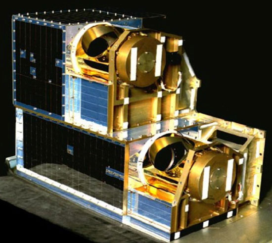
Figure 1: AMSU-A
Our people assisted with the Advanced Microwave Sounding Units (AMSU-A & B) space flight instruments, which were multi-channel passive microwave radiometers that measured global atmospheric temperature profiles from the advanced TIROS-N spacecraft. Aerojet Electronic Systems (now Northrop Grumman) was responsible for the delivery of the AMSU-A to NASA / NOAA. The AMSU-A system provides information on atmospheric water in all of its forms with the exception of small ice particles, which were deemed transparent at microwave frequencies when this design was produced.
Under AMSU, the radiometric characteristics of the atmosphere were determined primarily by the absorption and emission characteristics of the oxygen molecule in the 50-60 GHz band of the frequency spectrum. Since the mixing ratio of oxygen is constant in the atmosphere, the contribution of a particular layer of the atmosphere to the total radiation detected by a space borne radiometer operating in this frequency range is primarily controlled by the air temperature and the product of two competing factors. The factors are the emission per unit volume; which decreases monotonically with height due to the decreasing air density; and the transmission factor of the atmosphere above the layer under consideration. The resultant product is a function which typically peaks at some height and decreases with distance away from the peaking altitude. By selecting frequencies with different absorption coefficients, weighting functions emphasizing radiances from preselected atmospheric layers may be obtained. The problem of profiling the temperature of the atmosphere then reduces to finding the most probable profile which, when weighted by the appropriate weighting functions, produces the measured brightness temperature values of the selected frequencies.
The AMSU-A sensor is a millimeter wave instrument, which passively monitors the radiation from the earth’s surface and atmosphere in the microwave portion of the spectrum. The AMSU-A was made up of two modules A1 and A2. Each was configured in the same fashion and consists of four major sub-assemblies:
1. Antenna /Drive/ Calibration Sub Assembly
2. Electronics Sub Assembly
3. Mechanical Structural Sub Assembly
4. Thermal Sub Assembly
In each module A1 and A2, the basic design of the sub-assemblies was the same differing only as a result of the specific frequencies. The total instrument was a 15-channel instrument. In one module, 13 channels exist; this was identified as AMSU-A1. These 13 channels measure higher frequency O2. Two separate and independent antenna/drive calibration sub-assemblies and electronic sub-assemblies are integrated with a single common mechanical structural sub assembly and thermal sub assembly. The AMSU-A2 module was a 2-channel module. These are low frequency H2O channels.
The cross track scanning of the earth scene was accomplished in a stepped fashion with a 165 millisecond at each of the 30 earth viewing angles, and a 384 millisecond at the cold and warm calibration angles. Stepping of the antenna between the last earth viewing position and the cold calibration position, the two calibration positions and the warm calibration position in the first earth viewing angle was accomplished in a rapid step fashion. A complete rotation of the antenna was accomplished in 8 seconds. During each rotation of the antenna, AMSU-A modules are calibrated with a cold reference by review of the cosmic background and a warm reference by review of an ambient RF target at a nominal 300ºK temperature.
Our people helped design and produce the parabolic reflectors (A1 Antenna) for the AMSU-A instrument. These parabolic reflectors were fabricated from detailed components of beryllium, brazed together in order to create the overall antenna. One of the key components was the parabolic reflector, which captured microwave energy and transferred it to the detector within the instrument. This was a precision creep formed surface, gold plated and metallurgically joined to the rest of the shrouding and shaft that kept the alignment of this antenna to successfully create the overall instrument. This can be seen in Figure 3, a companion instrument was also produced using the same technique. The other shroud was fabricated of beryllium and then coated with a mylar film to meet emissivity and absorptivity requirements. These precision antennae were an enabling factor in the overall instrument since the weight; moment of inertia and stiffness of these particular components were fabricated from beryllium, which allowed for smaller motors and encoders to be used. This allowed the overall program to hit its weight and performance targets.
These antennae are currently flying on the TIROS-N weather satellites and are successfully providing meteorologists the information necessary to predict weather and weather patterns on the earth.
Block Diagram
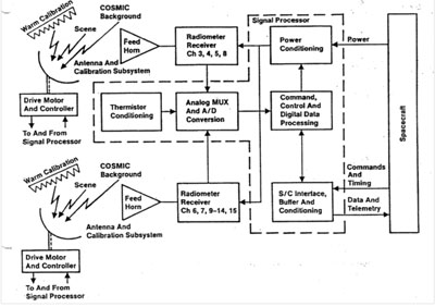
Figure 2: A block diagram illustrating the layout of the two A1 & A2 modules
Peregrine is a specialty design, fabrication and test company specializing in spacecraft and R&D components. We primarily rely on SolidWorks as our modeling software and for its simulation capabilities. Peregrine has produced many spaceborne and R&D assemblies and have been responsible for not only fabrication; but for the design, simulation, fabrication and qualification of those components. Peregrine supports many commercial, NASA, NOAA and military satellite programs.
Peregrine’s personnel were involved in the AMSU –A project in support of Aerojet Electronic Systems. In addition, British Aerospace produced a complimentary AMSU-B instrument for EUMETSAT. Peregrine’s people were an important part in producing these two instruments.
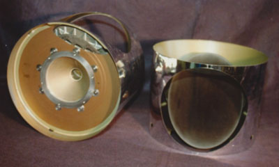
Figure 3: AMSU-B Hardware designed and fabricated
The Development of the Liquid Flow Through Modules for the F-22 Common Integrated Processor 15 Jul 2013, 7:30 pm

Figure 1: F-22 Raptor
Our engineering and manufacturing people assisted in the development of Liquid Flow Through (LFT) for the Air Force’s F-22 Fighter Aircraft. These LFTs were used in the aircraft’s Common Integrated Processor (CIP). Printed Wiring Boards (PWB) were laminated to Liquid Flow Through (LFT) heat exchangers creating Line Replaceable Modules (LRMs). The LFT heat exchangers were the component our people assisted in developing.
From the beginning of the program, the Air Force had enforced stringent integrity requirements through their Avionics Integrity Program (AVIP). They were similar to the design practices followed with Advanced Design for Quality Avionic Systems (ADQAS). The area of greatest concern, from an integrity point of view, was the durability of the solder joints after low-cycle fatigue from thermal cycling. The ceramic packages on the PWB’s have a coefficient of thermal expansion of 6 ppm/ºC, considerably less than the 21 ppm/ºC for the PWB on an aluminum heat exchanger. Although compliant gull-wing leads were used, the mismatch in the CTEs of the package and the PWB were shown to be enough to cause failures in the solder joint. By using a heat exchanger with a low CTE, the effective CTE of the PWB could be reduced enough to ensure the solder joints would survive the thermal environment. This required replacing the traditional aluminum heat exchangers with aluminum-beryllium heat exchangers.
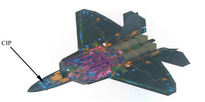
Figure 2: Internal View of F-22 System’s (Avionics in Blue)
Material Properties
Aluminum-Beryllium (Al-Be) is an aluminum alloy developed in the 1960’s under the trade name “Lockalloy” and used on the SR-71. The alloy combines the most favorable components of both aluminum and beryllium (Al-Be) into a single metal. The alloy is made using powder metallurgy techniques. Al-Be has over twice the stiffness as aluminum, yet is 23% lighter. It is just as stiff as some ceramics and yet is almost as machinable as aluminum. The CTE for AL-Be is 14 ppm/ºC, versus 23 ppm/°C for aluminum. Al-Be also offers an increase in thermal conductivity.
Al-Be machines like magnesium and requires the dust to be captured. The chips can be recycled and it does not require post machine etching like pure beryllium. Al-Be joins like aluminum. It can be electron beam welded, brazed or bonded. It is finished like aluminum and can be alodined, painted or nickel-plated.
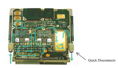
Figure 3: Populated LFT Module
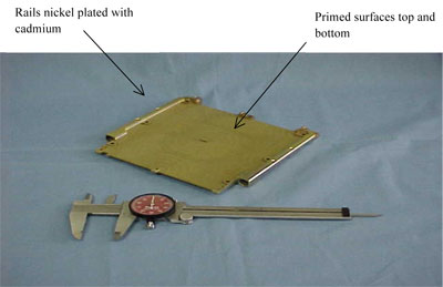
Figure 4: LFT Module
A major concern with choosing Al-Be for a brazed assembly was whether the material had all the processes fully developed and in place. The machining characteristics of Al-Be were fairly well understood, and nickel and other plating samples had been produced. However, the F-22 heat sink required vacuum brazing. The LFT heat sink is basically a pressure vessel that had Al-Be to Al-Be and Al-Be to Al Braze joints (the Al-Be to Al joints consist of Al-Be facesheets brazed to Al finstock). Test coupons for shear and tensile strength; along with burst; were developed, brazed and tested. The final heat exchangers were able to handle over 850psi internal pressure (385psi is the burst requirement and 285psi proof) and were subjected to 10,000 pressure cycles from 0 to 125 without failure (5000 cycles in the requirements).
In addition to the brazing, two surface finishes were verified. An epoxy coating type primer was chosen and tested for the surface treatment of the heatsink where the PWBs were to be laminated. The advantage of using the primer is that the surface preparation required to bond the PWB thereafter is virtually none, just a simple alcohol wipe. Making the LFT easy to process whereas typically with aluminum heatsinks an Ajax scrub is performed until a water break-free surface is achieved. Samples of Al-Be coated with this primer have passed over 500 hours of salt spray testing and yielded lap shear strengths higher than other surface treatments.
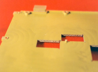
Figure 5: View of Internal Heat Exchanger with sections removed for examination
The Aluminum-Beryllium Alloy F-22 Liquid Flow Through Heat Exchangers underwent qualification testing per the specification and drawings. Piece parts were machined, brazed with internal finstock and then finished machined to final dimensions followed by coating.
After finish machining of the LFT heat exchanger, the rails were electroless nickel plated according to MIL-C-26074 Class 3, Grade A and then over plated with cadmium per QQ-P-416 Type 2, Class 1 with supplementary chromate treatment. The facesheets, where eventually the PWB’s and components would be bonded, were coated with the primer.
Qualification testing included proof pressure testing, pressure cycling, burst testing, and sectioning to examine the braze joints and plating interfaces and thicknesses.
The heat exchangers were visually examined, photographed, x-rayed, and pressured to a proof pressure of 280psi. One was then pressurized up to 1000psi and another was pressure cycled between ambiant and 125psi at a rate of 12 cycles per minute. Both were visually examined after testing, one was subsequently tested for 96 hours in salt fog per ASTM-B-117 (5 % salt fog at 95 ºF) and examined for signs of corrosion. It was then sectioned to determine internal corrosion at the quick disconnect locations. Another was sectioned to characterize the braze joints between the facesheets and fin stock and between the facesheets and rails. The various platings were also evaluated and measured for thickness. The LFT’s passed all examinations and were successfully qualified for use on the F-22.
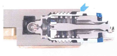
Figure 6: Magnification of 2.5X, cross section of quick disconnect in the LFT
Interface Plate for Cryocoolers 15 Jul 2013, 7:00 pm

Figure 1: Cryocoolers to cool satellite instruments
Some spacecraft instruments and detectors such as infrared systems and their focal planes require cooling down to cryogenic temperatures. There are three technologies that have traditionally been used to cool those focal plane arrays and instruments down to their optimum operating temperatures. Those technologies are stored cryogen cooling systems, cryogenic radiators, and cryocoolers. Stored cryogen cooling systems require the placement of a dewar on board the spacecraft. This dewar effectively maintains the cryogenic fluid until it is required for use. Cryogenic radiators are potentially effective down to about 75ºK. Cryocoolers are mechanical devices that require power to operate and to continue to operate. Cryocoolers can reach temperatures as low as 4ºK. Dependent upon the mission, each of these technologies would be under consideration. This project focuses on cryocoolers and the improvement of those coolers to make them more efficient and lighter weight.
Cryocoolers are electromechanical devices based on sterling, Gifford-McMahon pulse tube or Joule-Thomson effect. For the purposes of this case study, consider a cryocooler an exotic space borne refrigerator. Its purpose is to cool one singular device down to very low cryogenic temperature in the range of 4-20ºK degrees. Significant input power is required to effectively provide a small amount of cooling to these cryogenic temperatures. Anything that can improve the operating efficiency of these devices can have substantial benefits in reducing system power requirements and weight.
Peregrine has embedded Thermal Pyrolytic Graphite (TPG) by means of Liquid Interface Diffusion (LID) bonding into aluminum to yield over a 3.5 times increase in thermal conductivity over typical 6061T6 aluminum. It was determined that this would lead to an over 80-Watt reduction in input power for cryocooler designs providing a significant performance gain.
This innovation will reduce the mass of cryocoolers, reduce the required input power and increase a cooler system’s margin for a given cooling load. The Peregrine Falcon Corporation, significantly improved the overall performance of pulse tube cryocoolers for Long Wavelength InfraRed (LWIR) and Very Long Wavelength InfraRed (VLWIR) sensors (operating from 40ºK down to <10? K) by enhancing the thermal conductivity of structures internal to the cryocooler. This enabled more efficient heat removal. Peregrine’s proprietary process for incorporating Thermal Pyrolytic Graphite (TPG) was used to increase the heat flow in critical areas, and thereby improve the cryocooler performance, without increasing the overall mass.
The advantages of LWIR and VLWIR sensors in missile defense include passive Above The Horizon (ATH) detection and tracking of Re-entry Vehicles (RVs) and decoys at lower temperature and at greater range.
During midcourse missile flight, passive IR tracking and discrimination of ballistic missiles, re-entry vehicles, and deployed decoys are difficult without the use of sensitive LWIR and VLWIR focal planes. By collecting photons at longer wavelengths, emitted by cold bodies, a vast improvement in identification, discrimination and targeting capability can be realized. The use of multiple spectral bands can also be utilized to enhance sensor platform ability to measure cold body temperature and cool-down rates, which can further enhance the ability to separate lethal objects from decoys.

Figure 2: Model of a three-stage cold head showing the location of the pulse tube cold head warm end relative to the thermal rejection surfaces.
Consider two cryocooler designs, both with a thermal rejection temperature for the cooler of 300ºK, one with a 10ºK temperature rise above that at the base of the cold head and the other with a 33ºK temperature rise. These correspond to cooler designs with and without the use of TPG in the center plate. The cold head rejecting to 333ºK requires 17.7 % more input power for the same cooling load than the cold head rejecting at 310ºK does, corresponding to a difference of 88.4 Watts in a 500 Watt cooler.
To reduce the temperature rise between the pulse tube cold head and the thermal rejection surface, we incorporated TPG into the interior of the cryocooler “center plate.” This resulted in increased thermal conductivity producing a lower temperature drop and lower cryocooler mass. Its net effect was to reduce the mass of the cryocooler at the same time it reduces the required input power for a given cooling load.
We embedded TPG in the thermal path between the warm end of the cold head and the thermal rejection surfaces within a matrix of aluminum to create a very high thermal conductivity “Center Plate”. The TPG and aluminum were joined based upon a Peregrine proprietary Liquid Interface Diffusion bonding process (LID bonding). TPG and aluminum do not readily metallurgically bond to each other and therefore Peregrine utilized a vapor deposited intermediate layer. Previous industry attempts to embed TPG within aluminum were based upon a mechanical bond that is in essence a shrink fit of the aluminum around the TPG. This does not create a metallurgical joint and can lead to separations as the TPG and aluminum slide over each other during temperature excursions thus compromising the TPG’s high thermal conductivity. Peregrine utilized a thin vapor deposition of an intermediate material that was compatible to both and created a metallurgical bond under pressure and temperature.

Figure 3: Center Plate, TPG embedded in aluminum.
Peregrine successfully embedded TPG within aluminum (as seen in Figure 3) to create a passive high thermal conductivity solution reducing a temperature gradient by 34°C. Also by using TPG within this system, we had a weight savings of at least 17kg (37.4lb). We designed, analyzed, fabricated, examined and tested the center plate for performance against the requirements and were able to exceed all.
Gimbaled Pointing Systems 15 Jul 2013, 6:30 pm

Figure 1: Precision gimbals and pointing systems
In targeting roles, aircraft like the Airborne Laser and helicopters like Comanche can be equipped with gimbaled active or passive devices with a fully integrated suite of displays, command controls and communications.
In direct reference to Comanche, the advanced infrared (IR) sensors had twice the range of OH-58D Kiowa Warrior and AH-64 Apache sensors. The Comanche was equipped with the Apache Longbow fire control radar and the Helmet Integrated Display and Sight System (HIDSS). The fully integrated avionics system allowed tactical data to be overlaid onto a digital map, allowing the crew to devote more time for target detection and classification. A triple-redundant fly-by-wire system automatically held the helicopter in hover or in almost any other maneuver, reducing workload, allowing the pilot to concentrate on navigation and threat avoidance. A hand-on grip permitted one-handed operation.
The Comanche incorporated more low-observable stealth features than any aircraft in Army history. The Comanche radar cross-section (RCS) was less than that of a Hellfire missile. To reduce radar cross-section, weapons were carried internally, the gun was rotated aft and stowed within a fairing behind the turret when not in use, and the landing gear was fully retractable. The all-composite fuselage sides were flat and canted, and rounded surfaces were avoided by use of faceted turret and engine covers. The Comanche’s head-on RCS was 360 times smaller than the AH-64 Apache, 250 times less than the smaller OH-58D Kiowa Warrior, and 32 times smaller than the OH-58D’s mast-mounted sight. This meant that the Comanche would have been able to approach five times closer to enemy radar than an Apache, or four times closer than an OH-58D, without being detected.
Lockheed Martin Missiles and Fire Control developed an EOSS (electro-optics sensor system) which was comprised of: EOTADS (electro-optics target acquisition and designation system), including a solid-state TV sensor, two-color laser rangefinder/designator and second-generation focal plane array long-wave FLIR (forward-looking infrared); and NVPS (night-vision pilotage system) with a second FLIR for Comanche.

Figure 2: Machined Gimbal
Peregrine worked with Lockheed Martin out of Orlando, FL on the EOSS / EOTADS system for Comanche. Peregrine had the responsibility of producing the gimbals for this high performance system. In particular to this case study, Peregrine produced complex gimbals as can be seen illustrated in figure 2. These were high precision components made from beryllium-based material. Precision machining was required in 5-axis mode to achieve the overall geometry requirements for the components, plus precision alignment of the bores and bearing locations. Directly involved with the overall production was our manufacturing and design engineering team that relies heavily on SolidWorks for modeling, 3D manufacturing, simulation and final inspection. Some of the complex geometries involved with the gimbals shown herein, required complex 3-D dimensional verification obtained by importing solid models into our dimensional verification system and validating spatial requirements.
The components supplied to Lockheed Martin Missile and Fire Control systems for the Comanche EOSS / EOTADS enabled their system to rapidly target and track objects. Peregrine successfully delivered the gimbals for the Comanche system meeting weight, performance and overall quality objectives.

Figure 3: Schematic of Comanche Helicopter
Peregrine is a leader in the development and production of high performance gimbals for optical systems for use in military and commercial high performance applications. Our expertise spans over 25 years.
Peregrine has produced space-qualified gimbals, pointing systems, optical structures and air frame mounted gimbals for FLIR systems. These high performance applications demand a high degree of accuracy and operation under extreme environments. Our products have supported infrared optical systems, visual optical systems, and x-ray optical systems. We work with our customers to produce custom gimbal designs to meet mission specific needs.