Add your feed to SetSticker.com! Promote your sites and attract more customers. It costs only 100 EUROS per YEAR.
Pleasant surprises on every page! Discover new articles, displayed randomly throughout the site. Interesting content, always a click away
Model Ships & Boats by
Thomas J. LauriaRestoration of a Large Sailing Model, 1 23 May 2014, 11:43 am
RESTORING AN ANTIQUE SAILING MODEL OF THE SCHOONER
SADIE MORSE

In the “ON THE WORKBENCH” section of the site, I’ve always highlighted a new project, L. A . Dunton. Emma C. Berry, Kate Cory. But I thought since I have been doing a lot of repair work lately, why not chronicle a repair project. I’ve left the comments option on for these posts, if you’d like to leave a question or comment. Tell me what you’re thinking. So, here is my latest big project:
The Restoration of the large Sailing Model, Sadie Morse.
Note: I undertook this project at the request of a private owner, not a museum or historical institution. He bought the model in “as is” condition at auction and wanted to have it repaired and stabilized. This is not a museum level conservation. The point of this repair was to make a visually acceptable restoration on an antique using reversible and non-reversible techniques and materials. So now, let’s have a look at Sadie.

PART ONE
FINDINGS
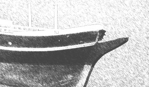
My initial examination of the model was at the home of its current owner. This model is fairly large, being 51-1/4” from the peak of the foc’sle deck to the taffrail and a bit over 5 feet tall. There was no original rigging left on the model and the rigging that was there was done by the client solely as a means of keeping the spars in place, temporarily.

Figure 1 Sadie, before repairs began.
The model portrays a vessel of the type that was very popular in the coastwise trade from the late 19th to the early 20th century. Typically vessels from this period and configuration were in the 60-90 foot range. My guess for the size of the ship this model represents would be about 75, or possibly 80 feet. And my estimate of its age puts it at about 1880 to the turn of the 20th century, or perhaps shortly thereafter. I believe the model is nearly that old, as well. There is a name hand written on the starboard quarterdeck topgallant rail. It reads, “Sadie Morse”. I did a quick internet search for vessels with that name, but found nothing. The client also searched and found a link to a family named Morse from Maine. And there was, indeed a girl named Sadie born into this family in the 1880’s. The family was also involved with ship and boat building in Maine, but there was no mention of a vessel named for the girl. As of the writing of this document, there has been no further information concerning the validity of the name as it pertains to a specific vessel.
CONDITION OF THE MODEL
Upon its arrival to my studio, I had a chance examine the entire model in detail and assess its condition, as well as form a plan for the repairs.
The first thing I noticed was the amount and condition of the paint. It was very clear that the current paint scheme is not the original. However, this was done a long time ago, as there is ample evidence of the paint breaking down, mostly I would guess, from the model not being adequately hydrated over its long life. One could suppose that the newer paint scheme was applied by someone other than the original builder/owner. And that is certainly possible. It is also just as likely to have been done by the builder. He (or she) may have had the model for so long that they tired of the original colors and gave it a look that suited their changing tastes. There really is no way to know what the truth about this is, except the one indisputable truth: This paint is old. The client and I agreed that the paint would be left as it is, with one exception. Sometime in the model’s life, a previous owner had the room the model occupied painted. The model must have been left uncovered because the foc’sle deck, the main deck, the quarterdeck and the top of the aft cabin were speckled with white paint. This was obviously cast off from a paint roller. This is the kind of damage that can happen very quickly and without the knowledge of the person causing it.

Figure 2 The broken garboard has been removed, exposing the frames. Note that, even in the photo, the paint looks dry.
CONDITION OF THE HULL
The hull is built plank on frame. The frames are roughly formed by steam bending and a number of them have hard bends in them, rather than smooth curves and beveled edges. They are attached to the keel by means of hide glue and wrought nails. Large amounts of hide glue was used in an effort to bind the ill-fitting frames to the keel. Hide glue is not meant to fill gaps and correct bad joinery. It gets its strength from solid surface to surface contact between the mating pieces. As a result, as long as the nails held, the frames held. But as the nails began to rust and corrode the weakened glue joints began to fail. I found many loose frames lying in the hold of the model. Moreover, the builder did not follow standard ship building practices when he built the hull. There are no clamps, stringers, ceiling planks or keelson to internally tie the structure together. What this means is that the hull is now held together by rusted nails and the very brittle glue of the outside planking. If you remove the planks, the frames will fall apart. Another issue related to the hull structure was the discovery of a missing section of the garboard plank on the starboard side of the model. About 5 inches aft of the forefoot, there was a 5” or 6” piece of the garboard plank missing. The break appeared to be quite old as the remaining edges were slightly rounded over and the bare wood was definitely not clean. All of the wrought nails holding this plank in place were rotted through and with frighteningly little effort the entire aft section of the plank came cleanly away from the model. This exposed the interior of the bottom of the model. Here, I made another discovery. The interior of the model from the floor of the frames up to the underside of the deck and from the break of the quarterdeck all the way to the transom was packed solid with nesting material of some rodent. It was not be a stretch of the imagination to think that the break in the garboard had a lot to do with these creatures choosing this model as a great place to raise a family. Fortunately for The client (who has had the model in his house) and for me, who has to clean the model, it was clear the nest was abandoned many years ago. I did, however, find a few almonds, still in their shells that were left behind.

Figure 3 A cozy little nest, for a while, anyway.
POST TWO POST THREE POST FOUR POST FIVE POST SIX
The post Restoration of a Large Sailing Model, 1 first appeared on Model Ships & Boats by.
Restoration of a Large Sailing Model, 2 22 May 2014, 6:24 pm
SAILS, SPARS AND RIGGING

I will discuss my findings in the order above and try to address them from fore to aft, top to bottom and port to starboard, as needed.
SAILS
When The client and I discussed how the repairs would be carried out, he mentioned that he might like to have a suit of sails made, while I was rebuilding everything else. I resisted this idea initially because I could see no evidence the model ever carried sail. However, when I got the model into the studio, and looked it over, it quickly became apparent that this was, at one time, a sailing model. When I informed The client of the discovery, he asked that I put sails on the model. And so the model has a new suit of “canvas”.
HEAD RIGGING
THE BOW SPRIT AND JIB BOOM both appear to be original to the model and are in good condition. There is no obvious evidence of a dolphin striker, although given the number of head rigging attachment points in the bows of the model it would seem logical that there would have been one.
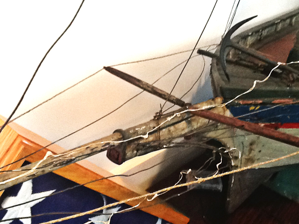
Figure 4 This shows the 2 misplaced spars on the jib boom.
On the top side of the jib boom, there is a wire traveler about 2-1/2” long and ¼” tall. Attached to this traveler, there were two spars: one looked original to the model, the other did not. I surmised that these were used as jib boom whiskers or spreaders for the head guys, port and starboard. But, they could not have served in that function while being attached to the wire traveler. In order for these two spars to act in that capacity, they would need to be in a fixed position, not allowed to move. After consulting sail plans for similar vessels from the same era, I found the wire traveler was a snotter used to trim the forestay sail (also called a jumbo on fishing schooners). The forestay sail would have been laced on to a club boom. The forward end of the club boom would be fitted with a goose neck and that gooseneck would have slid forward or aft on the snotter, as needs dictated. Also, upon closer examination of the two spars, I found the original spar had clearly been cut down and its aft end altered in shape. The non original piece, which I am assuming was made by the same person who carried out the other repairs, was similar in length, only to the original.

Figure 5 This image shows how the snotter and club boom should be rigged.
POST ONE POST THREE POST FOUR POST FIVE POST SIX
The post Restoration of a Large Sailing Model, 2 first appeared on Model Ships & Boats by.
Restoration of a Large Sailing Model, 3 21 May 2014, 11:27 am

Just finding out what needs to be done took quite a long time with this model. Here, we continue the findings, moving further on with the spars and the aft cabin.
THE FOREMAST had sustained some damage a long time ago. The broken section was at the top of the mast. It is called the masthead and it is where the lower mast and topmast sections overlap. There was no attempt to replace the missing section of the mast. They simply pushed the topmast further down on the lower mast and held it in place with a nail, causing still further splitting. I also believe that by the time this ill advised repair was attempted, the model had already lost its sails. I think this because if the sails had been present, the repairs made would not have allowed the sails and their rigging to be re-installed in their correct place.

Figure 6 The broken and then badly repaired foremast head.
THE FORE GAFF is not original to the model and was made slightly longer than would comfortably fit between the two masts, if it were actually required to function.
THE MAINMAST had similar issues to the foremast, but at the opposite end. When I examined the mainmast, I found a metal (tin?) sleeve about 2-1/2” long just at the spot where the main boom jaws would make contact with the mast. At first glance, this could be mistaken for a collar installed there to protect the mast from wear as the boom swung from side to side. However, I also noticed that the mast wiggled right at that spot. It was clear this was not meant to protect the mast. It was another less than proper repair. The sleeve was installed with 4 or 5 carpet tacks, some of which had to be filed down as they broke though the other side of the mast. Upon removal of the sleeve, I found the mast was broken into four pieces, one of which was missing.

Figure 7 Metal sleeve concealing the multiple breaks in the main mainmast.

Figure 8 Multiple breaks, uncovered.
BOTH THE MAIN BOOM AND GAFF are in good condition. The only thing that needs to be done is to attach blocks for the halyards and sheets.
THE AFT CABIN
As I mentioned earlier, the ROOF OF THE CABIN was speckled with white paint. This will be repainted. There are two base moldings on one side and one end of the cabin. These are not original to the model. A closer inspection revealed that the original molding was about half the size of the replacement. I was able to discern this because the “ghost” image of the original molding was still visible, both on the deck where the cabin sits and on the sides of the cabin.
Mr. Rogal asked if I could clean up the windows on the cabin. During a painting session, someone got quite a few smears and smudges on all the ports.

Figure 9 Aft cabin with the oversized molding and smudgy windows.
POST ONE POST TWO POST FOUR POST FIVE POST SIX
The post Restoration of a Large Sailing Model, 3 first appeared on Model Ships & Boats by.
Restoration of a Large Sailing Model, 4 20 May 2014, 10:10 am
PART TWO
From this point on, the actual repair work begins

For ease of transportation to my studio, all of the temporary rigging was removed, the model was dis-masted and it was packed into my car.
Once in the studio, many “before” photos were taken and there was much poking and prodding. Although this is not a scale model, I felt I needed to determine a rough approximation of the scale, given the many new parts I would have to produce and I would need to pick the right sizes for the rigging lines. I went on the assumption that this was a 75 foot vessel. For its overall size, it makes the scale roughly 1:19. This was how I calculated the sizes of everything I made for the model during this project.
It was during this early, exploratory phase that I discovered the broken garboard and the rodent nest. These two items were the first things I took care of, formally commencing the “repair” phase.
THE HULL
THE GARBOARD PLANK came off the model very easily. With that piece out of the way, I started dismantling the nest. This took about an hour. It was packed much tighter than I would have ever guessed. And, at the end of it, I had filled a large shopping bag more than half way up with the material.

Figure 10 One can only guess how long it must have taken them to gather all this into the hold of the model.
With the interior now cleared out, I had a much better idea of the condition of the hull. I was not encouraged. Many of the frames were loose and laying inside the model and many more are in precarious condition, at best. This was a sailing model, so it probably spent a fair amount of time in the water. And, even if it didn’t get used a lot, more than one hundred years of exposure to the elements and changing environmental factors have taken their toll on the iron fastenings and the hide glue.
I wish I could say that I was able to put all the frames back in their proper place, but they could not be re-installed given the extremely delicate condition of the hull’s internal structure and the very limited access I had to the model’s interior.
To that job properly, I would have to remove nearly all of the planking. Some method for stabilizing the shape of the hull would need to be employed. And addressing one frame at a time, remove the rusted nails, clean the old glue off and try to re-install the frame in its original position so that when the planking is put back, everything lines up. This type of work would take many times longer to complete than it took to build the original model. Needless to say, the cost would be astronomical and, given what little we know about the historical significance of this model, not really appropriate.
Considering what I said in the last three paragraphs, the prognosis is not grim, at all. There are still many sound frames remaining and the model’s active life as a pond sailor is long over. Which means it will now live the pampered existence of a static display model. In the hands of its current owner, it will have a temperate and stable environment. With a bit of care, the hull will last a good long time.
To repair the garboard, I machined a piece of pine roughly 5/32” thick. I dressed the ends of the original pieces of the plank. Then fit and glued the new patch in. I chose to use epoxy as the glue for two reasons: first, it is very strong, sets quickly and it tolerant to small amounts of dirt and debris. And the more important reason to me was that I was not going to be able to use any nails, as the original builder did. I was going to have to rely on the strength of the adhesive to bond three less than perfectly fitted parts and have it be strong enough to be worked into shape and then last over time. Yellow glue or white glue would not have worked, here. I purposely left the patch overly thick because I wanted to be able to contour it into the original pieces at both its ends. When the shaping was done, I primed and painted it.

Figure 11 New garboard installed and painted. Note the six “nail holes” with rust stains. There are no actual nails in there.
Even though this patch is on the bottom of the model, I wanted it to look as much as though it belonged there as possible. So, I made six false nail holes and painted them in with the appropriate rust colored tones.
I could now turn the model right side up and address the other issues on the hull.
THE WINDLASS BRAKE on the foc’sle deck was missing one of its handles. A new one was made and fitted into the hole.


Figure 12 Windlass Brake Figure 13 Brake with new handle
As mentioned earlier, the decks and the cabin roof needed to be over painted. I mixed up suitable amounts of the shades I needed and applied them only thick enough to cover most of the white speckles on the surfaces. I made no attempt to replace missing paint on the rest of the model.
THE CABIN needed a base molding around its perimeter. I suspected the molding that was on it was not the original. And, I had my suspicions confirmed when I removed the cabin from the model. On the quarterdeck, I could see a paint line and a shadow where the present molding sat. It was about 3/16” wide, half the width of the current molding. I discovered a similar situation when I removed the molding from the cabin sides. There was clearly, a ghost image of the original molding, also about 3/16” high. I ripped a piece of pine (most of the model seems to be pine and cedar) to the original dimensions and gave the outer edge a 1/8” radius. After gluing the new moldings in place, they were primed and then painted with the same color as the cabin roof.
Next to be dealt with was the forward end of the cabin. There was a 1/16” thick piece of white oak nailed to the forward end of the cabin as a means of finishing off the cabin-to-quarterdeck joint. It only had one of its two nails left holding it in place and it was certainly not original to the model. I removed it, not to be re-installed. I replaced it with a piece of pine, 1/16” thick with a camber on the upper edge that matches the roof camber on the cabin. It overlaps the break of the quarterdeck by about half. This was painted to match the moldings and roof.

Figure 14 This photo was taken to show the repairs to the mainmast, but it also shows the forward end of the cabin with the ghost image of the molding and the oversized replacement molding, just to the left.

Figure 15 New moldings and paint to finish off the cabin.
PART ONE PART TWO PART THREE POST FIVE POST SIX
The post Restoration of a Large Sailing Model, 4 first appeared on Model Ships & Boats by.
Restoration of a Large Sailing Model, 5 19 May 2014, 11:43 am
THE SPARS

The majority of the time repairing this model was spent on the spars, sails and rigging. As I did earlier, I will outline the repairs from fore to aft and port to starboard. THE BOWSPRIT AND JIB BOOM were in good condition and needed no repairs. There was no obvious evidence of there having been a dolphin striker on the model, but it was usual for ships of this period equipped with a jib boom to have one to help carry the extra rigging normally associated with that spar. It was not a hard and fast rule, but it was a practice of the time. I made the piece and installed it under the bowsprit cap. It was painted to blend in with its surroundings.

Figure 16 New dolphin striker and some of the head rigging.
Next I removed of the two spars attached to the snotter on the jib boom. The snotter is the piece of wire highlighted by the arrow in the photo, above. I noticed that the two spars were not made by the same person. One was obviously original and had been altered, or perhaps it was broken a long time ago and a subsequent owner misinterpreted its function and cut it down to give it a new job. The other was a clear and erroneous addition in an attempt to give the model a style of head rigging that belonged on a much larger and older type of vessel. In the “before” photo in Part One, you will see the original spar is on the left. This spar started life as club boom, a much larger spar laced onto the foot of the forestay sail. One end of the boom would be attached to the snotter by means of a goose neck or ring and shackle arrangement and the other end would have a couple of sheave (pronounced shiv) blocks rigged to be a sheet for the sail/boom combination. I made and painted a new club boom and used the original “gooseneck” to attach it.

Figure 18 Here, the differences are clear, as is the alteration to the aft end of the original spar.

Figure 20 New Club boom and sail installed on the model.
To repair the FOREMAST, I had to create a scarf joint. I estimated how much new material I would have to add on to the foremast’s head to make it look proportional to the mainmast. I ripped a piece of pine stock, slightly over-sized and made matching diagonal cuts in the new stock and the foremast. When I achieved a good fit between the two parts, they were glued together and left overnight to cure. The next morning, I started shaping the new section of the mast. Next came painting and weathering to make it look as though it had been there a while. The photos below illustrated the repair.


Figures 21 and 22 are self explanatory
POST ONE POST TWO POST THREE POST FOUR POST SIX
The post Restoration of a Large Sailing Model, 5 first appeared on Model Ships & Boats by.
Restoration of a Large Sailing Model, 6 15 May 2014, 9:29 am

In Part One of this report, I outlined the damage discovered on the MAINMAST. The repair for this mast and the foremast are very similar. After determining how much needed to be cut away, a diagonal scarf was cut into the sound part of the mast. Again, using a piece of oversized pine, I cut a matching scarf joint and glued the pieces together. The process was the same for this as with the foremast. One notable difference was, because the mainmast’s damage was at the deck end, it had belaying pins, jamb cleats and a boom jaw rest attached to it. I managed to remove these from the broken section of the original section of the spar and re-installed them on the mast, once the repair was completed. Here are some photos.

Figure 23 First stage of the repair.
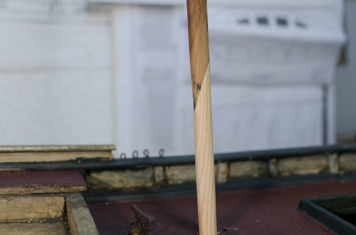
Figure 24 Part Two of the repair.

Figure 25 Mainmast back in one piece.
The masts were now repaired and ready to be re-installed. But, before I actually put them back on the model, I took the opportunity to install the futtock shrouds and topmast shrouds for both masts. It is so much easier to do this while the masts are off the model. Also, any rigging hardware in the form of eyebolts or stay bridles are likewise less troublesome to install when the masts are still free.
I like to use a laser level when installing the masts because it is very easy to see when they are properly aligned. Sadly, this was not possible with this model as the masts were not originally installed on the centerline of the model. They are about 3/32” off to starboard. I tried to get them a bit closer to the center by utilizing the oversized mast holes in the deck. It worked to a small degree, but in the end, it really didn’t make much of a difference.
THE STANDING RIGGING can now begin. The foremast shrouds were first to go on. The forestays and head rigging were next. The main shrouds and the triatic stay came after that. And the last thing to do is install ratlines.

Figure 26 Shrouds and the forestay on the model.
On a schooner, running rigging is fairly straightforward: halyards, sheets and downhauls. On a sailing model it’s even simpler, just halyards and sheets.
In preparation for the RUNNING RIGGING, I made a list of the blocks I would need. I determined the dimensions from my working scale of 1:19. Once the quantities and dimensions were worked out, I used maple and poplar to make the requisite number of single, double and treble blocks.

Figure 27 Blocks in varying states of readiness.
As the blocks were finished, I was able to re-install the spars on the model. They were rigged and hoisted to their finished locations. With the booms and gaffs in their proper spots, I could take the measurements for the sails.
As a rough guide to making the sails, I used the sail plan for another schooner from the same period, the Alice S. Wentworth. The Wentworth was built in South Norwalk, Connecticut in 1863, but was completely rebuilt in Wells, Maine in 1904. This puts these two vessels in roughly the same time span, and geographical locale. Because of its regional relationship to this model, the Wentworth’s plans were of much use to me in this project.
After taking all the measurements off the model, I made templates for each sail, using strips of basswood glued together. I made the sails from linen, architect’s linen. After the starch was removed the material was washed and dyed a slightly yellowish-brown color and washed again. It was ironed flat and the sail shapes were transferred by use of the templates.

Figure 13 Sadie’s sail templates.
At this point, THE SAILS are ready to be sewn up. It was time to make a few decisions about how much detail to put on them. Should I put in panel lines and reef points? What about boltropes and cringles? In the end, I decided against these details because I tried to put myself in the position of the original builder and think about what would have been available to me, at the time, and what my goal was. Most old sailing models had/have the simplest of sails. They were usually quickly fabricated from old or purloined bed sheets. Remember, by the time our model shipwright got to this point in the building process, he was probably getting a bit impatient to take his new creation sailing. In the examples I’ve seen of antique sailing models that still had their original “canvas”, most had very plain sails. So, I thought it more fitting to keep them simple. Only simple hems were sewn in around the perimeters.
Before I actually got to making the sails, I had the impression there were not enough mast hoops to accommodate the main and fore sails. However, when it came to install the sails the spacing of the 6 on the foremast and 7 on the mainmast looked right. I was happy not to have to guess how many there might have been, originally.
They are a bit on the tight side. Usually, mast hoops are sized about 20% bigger in diameter than the mast they are going on. These were just barely big enough to do their job, but they do work.
With the sails now on the model, the only thing left to do is coil up the ends of the rigging lines and give the model one last dust and vacuum.
CONCULSION
A large part of what I do as a professional ship model builder is repair work. And the Sadie Morse was a big job. One of the more rewarding aspects doing a large project like this is I find that as I am working on a model, becoming familiar with it. I start to see its strong points and charms, the kinds things not necessarily obvious to the casual observer. The model has a wonderful sheer, not at all exaggerated, as is so often the case with folk models. She was probably built without plans and if there was, indeed, a real schooner named Sadie Morse, then the person who made this model clearly had great affection for that vessel. And if there were no real schooner called Sadie Morse, then maybe he was building the ship he always wanted to see but never did. However she came to be here, it is clear the Sadie Morse was built by a loving hand that took great care to insure we see her best attributes. She is strong, very salty and has a sturdy grace that the best working vessels always seem to possess. A quality that says” I may be working class, but I do it so well.”
MATERIALS USED IN THIS REPAIR
Woods: Pine and maple
Paints and Finishes: Amber shellac, Liqutex artists’ acrylics
Adhesives: Devcon epoxy, Zap-A-Gap cyanoacrylate, Elmer’s white glue
Sail cloth: linen
Rigging line: Linen, Steam tarred linen, steam tarred cotton, silk, cotton
Dyes and Tints: Wood; Behlin aniline dye. Fabric; RIT fabric dye
POST ONE POST TWO POST THREE POST FOUR POST FIVE
The post Restoration of a Large Sailing Model, 6 first appeared on Model Ships & Boats by.
Ships in Scale Magazine 26 Nov 2013, 12:40 pm
The November-December issue of Ships in Scale magazine has the first part of the article I wrote about building the Kate Cory. It’s also the cover story (my first)! It seems they plan to publish the rest of the article over the next two issues. So, January-February, then, March-April will see the article complete. It is available through hobby shops and from Seaways Publications. You can order a single copy of any of their past or present issues, or subscribe by visiting their website: http://www.seaways.com/

The Jan-Feb 2014 Issue of Ships in Scale magazine is now out and has Part 2 of Scratch Building the Kate Cory. The final installment will be in the March-April issue. If you are following the progress in the magazine, let me know what you think. Drop me a line, either here or from the “Contact me” page.

Ships in Scale magazine’s March/April issue is now available and it contains the final installment of “Scratch Building the Kate Cory”.

The post Ships in Scale Magazine first appeared on Model Ships & Boats by.
Building the Kate Cory 11 May 2013, 3:49 am
Hull and Deck Details
Here you’ll find some of the “whys” and “hows” of scratch building this sweet little whaling brig.
The Hull
The lines drawing I used for this model had the hull shape drawn to the inside of the planking. Not being a big fan of plank on frame construction, I decided to do a solid core and plank it up to the finished dimensions. I started by making a waterline lift type of core up to the level of the sheer plank (Kate Cory, hull 1). Next, timberheads were added and the break at the quarter deck installed(Kate Cory, hull 2). Finish planking and sheathing came next. You will notice in the photos that there are two distinct patterns for the planking. Above the waterline, the hull is planked much the way you’d expect. But, below it was planked to represent the 1”x12” pine sheathing applied to hulls prior to being coppered. Why bother with this detail, only to have it immediately covered by the copper? Pine sheathing was applied full sized and not spiled, which made it much faster to install. This is true for models, as well. It was also fastened to the hull of the model with much larger treenails than would be practical for the regular planking, further streamlining the process of building the hull out to the finished dimensions (Kate Cory, hull 3). And lastly, copper plates and paint completed the basic hull (Kate Cory, hull 4).
Stern Eagle
I carved the eagle from cherry and it is eight and a half scale feet (21/8”) from wing tip to wing tip, which seems about right for a vessel this size (Kate Cory, Stern Eagle 1). I originally gold leafed the bird, but the effect was overpowering for such a small item. I decided to remove the gilding and replace it with a bronzing powder. The powder is still pretty bright but much less so than the gold leaf (Kate Cory Stern Eagle 2).

Deck Furniture Construction
The method for building the deck structures was the same for all (Kate Cory, House). Pictured here, is the Fo’csle companionway. I made the panels for the structure solid, as opposed to beaded panels, mostly because I was not sure that they were beaded (Kate Cory, House 1 and Kate Cory, House 2). It was a common practice of the time, so either method may be right-no way to know for sure. The doors were made using rail and stile construction, much the way the full sized doors would have been built. The rails and stiles are .062” boxwood with a .020” kerf down the middle, into which the door panels (.020” pearwood) were inserted (Kate Cory, House, 3).

Tryworks
Like the steering wheel, discussed below, the tryworks presented a couple of opportunities for creative problem solving (Kate Cory Tryworks, 4, from forward).
The first was: how to convincingly reproduce the brick work. Commercially produced material was out of the question for two reasons. First, this is a scratch built model and, with very few exceptions, the builder should not be buying anything commercially produced. And second, everything I’d seen looked unconvincing, two dimensional and, well, commercially produced. My answer was to make my bricks out of wood (Kate Cory Tryworks, 1, Brick Sticks). In the first photo, you can see the “brick sticks” being applied in the traditional pattern to the trywork’s form. The mortar lines were kept consistent by using 28 gauge brass wire between the courses as a spacer (just visible at the ends of the courses). After painting and weathering (Kate Cory Tryworks, 2), the “mortar” was laid in. For this I used light weight spackle. It was pushed into the mortar lines and the excess wiped off with a paper towel. When I did this, it left a very slight grayish film over the bricks. This patina gave a bit of age to the bricks (Kate Cory, Tryworks, 3, Mortar and Copper). They now had a worn in look that I find appealing.
The second problem was how to make the trypots, the two large cauldrons held by the tryworks. Each trypot is about 42” in diameter and roughly 25” deep. I decided to make a master, make a mold and cast them. The master was made very quickly and easily from modeling clay. Next, I made the mold from the master then cast the trypots using a two part resin. Sad to say, I didn’t think to take photos of this part of the process, but results are just visible in the finished shots.

Steering Wheel
The steering wheel was an aspect of the model that caused a lot of head scratching and blue language (Kate Cory, Wheel and Binnacle). I had never had to make a wooden wheel with turned spokes and was not quite sure how I was going to do it. I found my solution in the Nautical Research Guild’s, “Ship Modeler’s Shop notes II”. On pp 147 148, John Bobbitt outlines his method for making a wooden ship’s wheel ( Wheel 1, Wheel 2, Wheel 3). I adapted his method slightly to suite my need for this model and after only five attempts, I ended up with a passable representation of a “mahogany” steering wheel. The hub and spokes are cherry and all the rim components are pearwood. There are 27 individual parts to the steering wheel, itself, exclusive of the drum and stanchions.

Standing Rigging
Just about all the standing rigging on this ship had some or all of its length served ( Kate Cory, Fore Shrouds).
There is no worming and parceling on my model, only the serving. It was accomplished with the aid of a serving machine which I made to be attached to my lathe (there are photos of the machine in use in the “Emma C. Berry” gallery). . In this photo, you can see the first shroud is served for its entire length, while the others are served only enough to go round the deadeye and create the doubling.

Blocks
Blocks were made from either boxwood or white holly and stropped with brass or copper wire that I ran through a rolling mill to flatten. This photo shows the steps in the process (Kate Cory, Blocks for Notes).
Rigging Hardware
All the rigging hardware I made from scratch. The making of the blocks I outlined earlier. The deadeyes, hearts and fairleads are made from ebony (old piano keys). The shackles, split rings, eyebolts, thimbles and block straps are made from brass or copper wire (Kate Cory, Jib Halyard Block).

Sails and Spars
: Here is the TopGal’nt yard and sail. It is typical of all the spars and sails on the model (Kate Cory, T’G’lnt Sail, Kate Cory, T’G’lnt Sail, aft side and Kate Cory T’G’lnt Sail, close up).
The spars were made from either boxwood or maple. All the jackstays were made from boxwood. I elected to leave off the studding sail booms and their associated hardware. If I were working at a larger scale perhaps I would have included them. But at this scale, I think their inclusion would have been visually excessive. Also, it was not know for certain that Kate Cory actually carried them.
The sails are made from a special paper call silkspan. It is a very thin and very strong for its weight. And best of all, it stands up to water, an absolute necessity when making furled sails (Kate Cory, Two Lower Yards). It can also be painted or worked into various shapes when put over a form and moistened.
Scale patterns were made for each sail with tabling, panel lines and attachment points for the sail handling lines all marked out. The pattern was transferred to the silkspan, which had been given a thin coat of acrylic paint to make it look more like canvas. All the details were then glued on or penciled in, as needed.
The post Building the Kate Cory first appeared on Model Ships & Boats by.
Building the Kate Cory, Part 2 10 May 2013, 12:06 am
Whaleboats
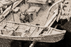
Kate Cory carried four whaleboats; 3 active and fully equipped boats which hung from iron davits and 1 spare boat carried on the “featherboards” off the stern (Kate Cory, Boats 3 and 4 from alow, astern).
I chose to model boats of the type made by the James Beetle Boat Yard of New Bedford, Mass. This was strictly an aesthetic choice on my part. I have no way of knowing whose brand of boats the ship may have carried. Since this model depicts the ship at about 1860, I have exercised artistic license and issued her Beetle boats. All four boats are 28’ 6” long, have a centerboard and a gaff rig.
The hulls were carved from basswood with all the details applied (Boat 1, Boat 2, Boat 3, and Boat 4). The paint scheme for the boats is dark green hull with a “color of choice” for the sheer strake. The boat header or mate got to choose. On this Kate Cory, the port bow boat has a yellow strake (Kate Cory, First Whaleboat), the port quarter boat is white (Kate Cory, Second Boat) and starboard quarter boat is black (Kate Cory, Third Whaleboat). Interiors I painted gray or blue for the ceiling planks and either buff or light green from the seat riser to the gunwales. The spare boat(s) carried on whaleships were generally painted a solid color until they were put into service. White lead as a primer was common with umber or gray for the interior and this is what I did for the spare boat here (Kate Cory, Spare Boat).

Whalecraft
All of the whalecraft for the boats on the Kate Cory are scale replicas of actual artifacts that were on display at the Nantucket Whaling Museum during the early 90s’. The folks at the museum kindly allowed me to measure all the gear in their fully equipped example of a Beetle whaleboat. That opportunity has given me a leg up, as it were, to produce models with an increased degree of historical accuracy (Kate Cory, First Whaleboat, amidships detail).
The post Building the Kate Cory, Part 2 first appeared on Model Ships & Boats by.
Building the Kate Cory, Part 3 9 May 2013, 12:43 am
Finishing Things Up
In Part 3, I talk a bit about how I dealt with filling the gaps in historical information. It will also conclude this series on the project.

Many people ask me how I feel about human figures on ship models. My answer is I really don’t care for them. So, who’s that guy standing by the fore shrouds (Kate Cory, Call him Ishmael)? That’s Ishmael. He’s not a permanent member of the ship’s company. After what happened his last voyage, he only goes on board when the ship is in port. He’s really there to keep me on track with respect to scale. Ishmael is 6’ tall, a bit large for the average height of the day, but not unreasonable. He proved to be a very helpful fellow to have around. There were plenty of times during the building process when I had photographic information on something, but no dimensional data. A good example of this situation is the group of tools on the cooper’s bench (Kate Cory, Bench, hooks, ground tackle AND Kate Cory, Coopers Bench). I had many good, clear photos of these items being used, but no sizes for any of them. I did, however, know the dimensions of other things in the photograph, like the tryworks and the height of the platform a crewman was standing on while using the tools. Gauging the height of the crewman standing at the tryworks and using myself as a full sized stand in, I was able to estimate how thick the handles of the tools were, or how far apart my hands would be while using them, and so on. Using this photographic algebra, I was able to come very close to the actual sizes of these things. When I thought I had things right, I’d hand them to Ishmael. If they looked proportional to him, as they did with the men in the pictures, I knew I had come very close to the real thing. Another example is the mincing tub you’ll find forward of the main pin rail on the port side of the ship (Kate Cory, Mincing Tub). I had to make the tub, the cutting board with the guides, a mincing knife and a small hand-held hook used to keep the blubber from sliding around. Here again, I had great photos, but no dimensions. By looking at the details in the pictures of the items in actual use, I was able to come up with all the dimensions I needed to make these parts. And once again, after getting Ishmael’s seal of approval, I found they could be installed on the model and they would look appropriate for the job they need to do.
At this point the model was just about done, except for some “tweaking” here and there.
So, I hope you’ve enjoyed reading this summery of the process. If you’d like to know more, there will be a full article coming out in “Ships in Scale” magazine in the near future. As soon as a publishing date becomes available, I will post it on my “Events” page. Keep an eye out!
And check back for notes on my next project, the schooner, Alice S. Wentworth.
The post Building the Kate Cory, Part 3 first appeared on Model Ships & Boats by.