Add your feed to SetSticker.com! Promote your sites and attract more customers. It costs only 100 EUROS per YEAR.
Pleasant surprises on every page! Discover new articles, displayed randomly throughout the site. Interesting content, always a click away
BioRealty, Inc.
Science and Technology real estate specialistsOverview of Aseptic Fill/Finish Manufacturing 11 Jan 2016, 8:02 am
by John Hamlin
Editorial note: This article was written prior to the new FDA Guidance for Aseptic Processing being published. The second part of this article to be published in the near future will reflect the new Guidance recommendations.
For a more recent article by John Hamlin, please see “Introduction to Cleanrooms“.
Article Overview
Provide an overview of the critical manufacturing process, aseptic fill/finish production of sterile products.
This article is the first of a two part series to provide a broad overview of the aseptic fill/finish manufacturing process. This first article will discuss the background of aseptic products and the operational requirements of the aseptic operation. This will include the personnel, cleanroom, preparations, and the fill/finish process equipment and a brief discussion of the sterile lyophilzation requirements. The second article will discuss the global regulatory and compliance requirements and will include the process validation of an aseptic manufacturing operation.
Introduction
Aseptic filling of sterile drugs, also know as sterile filling, still remains one of the most critical processes in biopharmaceutical manufacturing. This is due to its highly technique driven processes and the potential safety impact to the end user, usually an already compromised patient. There are only indirect safeguards for the sterility of the filled drug after it is stoppered and capped in the cleanroom.
Unlike terminal sterilized filled drugs, the stability of the aseptic filled drugs will be affected by steam autoclave, dry heat ovens, Ethylene Oxide, and irradiation, either Cobalt 60 Gamma or E Beam. Thus the need to utilize an aseptic process to fill certain biologicals, pharmaceuticals and biotechnology drugs.
The history of aseptic fill/finish processing is relatively recent with the sterility requirements for injectables being established in the 1920s and large scale biological manufacturing of blood and plasma products during WWII. Plasma products did have, and some products still use, a post-fill pasteurization process of low heat treatment of 60°C for 10 hours. Pasteurization does not provide sterility, but can reduce the contamination of fungi. Anti-fungicidal reagents were also added to parenteral drugs to help mitigate the contamination that was occurring with early aseptic processing.
Then in an effort to help improve consistency in aseptic processing, the Parenteral Drug Association (PDA) published its Aseptic Validation Technical Report in 1981 [8]. This was followed by the Food & Drug Administration (FDA) in 1987 with its Aseptic Processing Guidelines [1]. The International Society of Pharmaceutical Engineering (ISPE) published its Sterile Facilities as part of their Guidelines Series in 1999 [14]. Recently, the FDA published its Concept Paper: Aseptic Guidelines in 2003 [15].
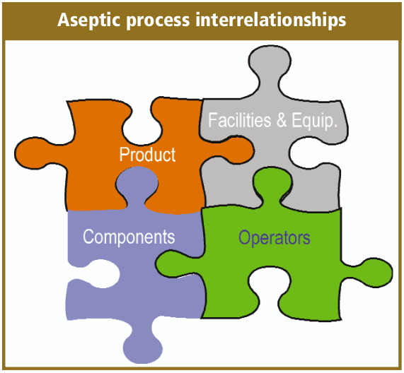
Aseptic filling is an aseptic process that requires the close coordination and complex interaction between personnel, sterilized product, the fill/finish equipment system, cleanroom and support facilities, and sterilized filling components.
There is also the perception issue for aseptic fill/finish, which is another reason for the many safeguards that I will discuss shortly, since micro contamination is not readily visible. Micro contamination is very small, and the surfaces that look clean and sterile may in fact not be. Thus the aseptic fill/finish processes are highly dependent on technique, detailed procedures, equipment and controls.
Regulatory Considerations
As with our industry, there are many global regulatory requirements for aseptic/ sterile fill/finish manufacturing. Although each country or geography has its regulatory guidance, we have not yet achieved full harmonization. Most of these are listed in this article’s appendix, and I will be only briefly discussing the current FDA 1987 Guidance. This FDA Guidance provides a couple of nice definitions for us.
“In aseptic processing, the drug product, container and closure are subjected to sterilization processes separately and then brought together Because there is no further processing to sterilize the product after it is in its final container; it is critical to the maintenance of product sterility that containers be filled and closed in an environment of extremelv high quality”
We also have written in the Code of Federal Regulation (CFR), section 21 CFR 211.113 (b) that states
“Appropriate written procedures, designed to prevent microbiological contamination of drug products purporting to be sterile, shall be established and followed. Such procedures shall include validation of any sterilization processes.”
Another section, 21 CFR 211.167 (a) states
“For each batch of drug product purporting to be sterile and/or pyrogen-free, there shall be appropriate laboratory testing to determine conformance to such requirements. The test procedure shall be in writing and shall be followed.”
Currently, the FDA has been expressing a number of concerns about aseptic manufacturing, citing all drugs recalled due to non-sterility over the last 10 years were produced by aseptic processing (Spring 2002). If you drill down in these recalls, you will find that there are a few companies who have multiple recalls, and that there are a lot of “documentation” recalls. These are situations in which the documentation or procedures had omissions and errors and as a result a recall was initiated. The consensus within our industry is that, in fact, we have been getting much better with our aseptic filling processes
Aseptic Fill/Finish
What can be aseptically filled? Virtually any solution, powder or suspension that can be terminally sterilized prior to the aseptic fill/finish process. Typically sterile drugs are aseptic fill/finish in molded glass bottles, tubular glass vials, tubular glass syringes and in Europe more than the United States, glass ampoules. Solutions can also be subsequently lyophilized in a sterile dryer to further stabilize drugs. The more unique the product or container system, the greater the technical or operational challenges that may ensue.
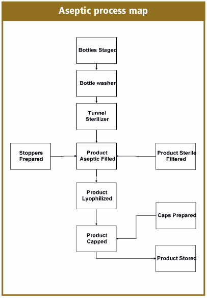
How do we complete the aseptic fill/finish process? You need to decontaminate the operational personnel, terminally sterilize the drug product, filling components, equipment change parts and sanitize the cleanroom and in-place equipment. Then bring it all together with good aseptic practices, and the simplified process maps look like the aseptic process map.
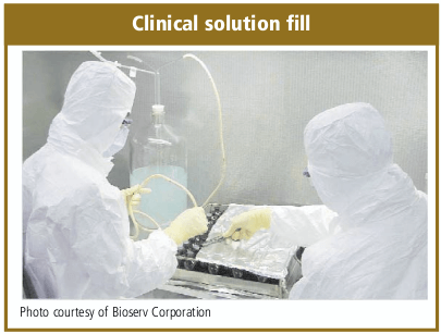
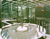
The aseptic fill/finish methods can vary between an early clinical phase hand fill (clinical solution fill photo), to small volume semi-automated filling to the fully automated high-volume over multiple day production batches.
Cleanroom Personnel
The personnel in the cleanroom are like the “double-edged” sword, they are absolutely necessary to complete the aseptic fill/finish process, but at the same time, provide the greatest microbial risk for a sterile product. You are constantly regenerating yourself, and in the process shedding a huge amount of dead skin and other particles. An average person is capable of shedding ten million particles per day. That is further compounded by the types of clothes worn and where you have recently been, such as what might be on the bottom of your shoes right now.
Thus the amount of investment that is made to limit the operational personnel risk to the sterile drug. Personnel are encapsulated with extensive sterile gowns and qualified gowning procedures. The cleanrooms have extensive unidirectional flow air currents to provide a barrier as well as sweep the potential contamination away from the exposed drugs.
Automated fill/ finish equipment is installed to reduce the amount of personnel who are present in the cleanroom during the aseptic fill/finish processing. Development of the current barrier equipment designs and the recent development of the isolator technology have been made to further isolate the exposed sterile drug from the operational personnel.
Lastly, the implementation of Best Aseptic Practices to provide personnel with methods, training and qualified procedures to further prevent microbial contamination of the sterile drugs.
The Best Aseptic Practices are a set of best practice methods for personnel to govem themselves as they move and function in the cleanroom environment while executing their processes. Aseptic practices will also incorporate the specific requirements for your aseptic fill/finish processing. Procedures are needed for both gowning and de-gowning processes, and state hygiene, training, qualification and re-qualification requirements.
Sterile outer garments are usually made of synthetic or natural materials, worn as an outer garment, which have low or no particle shedding or penetration characteristics. Most companies outsource their sterile garment preparation to a company who will wash and sterilize their garments, usually sterilize with Gamma. For low volume sterile garmenting requirements, you can utilize single-use sterile garment packs. The sterile outer garments act as a personnel filter to isolate the individual and their contaminants from the cleanroom environment and the sterile drugs.
Personnel who function in the aseptic fill/finish aseptic processing core will need to have completed a gowning qualification, especially to be present in the clean room core during a sterile fill operation. This would include the operational personnel, maintenance mechanics, quality assurance and quality control personnel, production management, engineers and technicians. The qualification should include training on the basics of microbiology and the Best Aseptic Practices. Typically, this is followed by a gowning demonstration, then a gowning critique of the person in training.
Final gowning qualification should be completed with multiple sterile gowning in the cleanroom with microbial testing inside the cleanroom. I recommend that the sterile gowning and microbial events should be videotaped to provide the operator with additional feedback and assist with the analysis of the gowning techniques. Gown qualification best practices require the gowning qualification to pass three consecutive microbial testing and successful media participation prior to being deemed gowning qualified. An example of a gowning process is provided in Table 2.
Facilities: The Cleanroom
The cleanrooms are controlled areas and in conjunction with the supporting utility systems and facility infrastructure, create the environmental envelop in which the aseptic fill/finish process operates. As with the other components of the aseptic processing, the cleanrooms area complex combination of physical rooms and areas, utilizing High Efficiency Particulate Air (HEPA) to create unidirectional air patterns, maintenance of positive pressure between rooms in conjunction with constant air changes, and sanitization processes. All of this operates with constant environmental monitoring (EM).
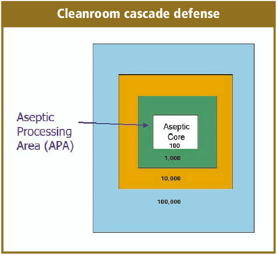
The cleanroom design will take into consideration the flow of personnel, product, equipment and components. Effective aseptic fill/ finish facility designs will take into account the flow of all of these from the receipt of raw materials at the warehouse through the facility to final warehousing. A very simplified illustration is the cleanroom cascade defense.
Very basic to the cleanroom design is the classification of the cleanrooms relative to the operation that is occurring within it as, well as adjacent to it. Harmonization of the regulatory guidelines for cleanrooms has not fully occurred yet, but I believe we are making some progress. In the cleanroom classification table (Table 3) is a very simplified comparison between the European Annex l and FDA classifications. I have referenced the various cleanroom compliance documents in the article appendix, and an in-depth discussion of cleanroom classifications was not intended for this article. You will need to know where your products are going to be distributed to select the proper guidance to follow, which for our industry and global products, usually means all of them.
Before discussing the cleanroom materials of construction or the Heating, Ventilation and Air Condition (HVAC), it is critical to first understand the flow of personnel, sterilized components and sterile product in developing the cleanroom design and operation. The flow requirements may vary with each sterile drug produced.
The personnel flow, as I discussed earlier, is very critical to maintaining the sterile environment. This would include the gowning, degowning and all of the necessary movements through all of the cleanroom facilities. It is ideal to ensure that the personnel flow is moving one-way; from gowning to operation and then degowning, cleanest area towards the “dirtiest.”
The one-way movement within the cleanroom, especially the sterile core for the aseptic fill/finish operation, is critical for all of the material, products and components. You will want to ensure your cleanroom design will eliminate two-way transfers from occurring concurrently, where sterile goods are physically passing “non-sterile” goods where there is a potential for microbial cross-contamination.
The movement of mobile tanks with sterile filter bulk drug presents challenges as well, as the exterior surfaces cannot be terminally sterilized with the drug enclosed before the aseptic fill/finish operation. The bulk tanks will require sanitization in airlocks or at other transfer modules. The sanitization processes for mobile tanks are challenged by the amount of fixtures on the tanks, clearance under the tank, and the tank wheel assemblies. Frequently the mobile tanks are segregated from the aseptic core and only the transfer of the bulk tank tubing connection necessary for the aseptic connection.
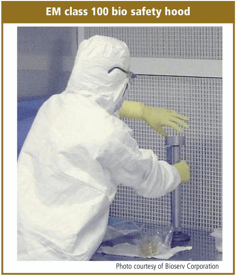
The equipment layout and flow will also influence the cleanroom design. The ideal aseptic fill/ finish system is a fully automated in-line isolator fill/finish system. The most difficult to manage and presenting the greater microbial risk, is a batch sterilization and completely manual filling process that occurs in a bio-hazard safety hood.
The equipment flow should also reflect the necessary sterilized set-up parts that will be changed for each sterile drug batch, such as the filling needles, stopper bowl and feeder components. The sterilized set-up components may require a specialized technician or mechanic to support the aseptic fill/finish operation. The ease in which the aseptic set-up can be accomplished and maintained can directly influence the quality of the aseptic fill/finish operation. You should eliminate any operations that require a sterile operator to reach over the fill line.
The aseptic core in which the sterile drug is actually exposed to the cleanroom environment is the most crucial area of a cleanroom, and warrants the most detailed attention to the design of the cleanroom. This is the area where the sterile drug is transferred from the filling needles to the sterile container. Typically the stoppering or closing of the container occurs immediately after, with the exception of when the drug requires sterile lyophilization. The requirements of the lyophilization process require the stopper be only partially seated on the vial.
For solution drugs after a stoppering process, sealing occurs immediately, usually with some kind of aluminium seal. The design of the cleanroom or equipment would include a barrier between the stoppering and sealing processes to minimize any potential aluminium contamination.
Another variation for sterile drug solutions is the use of Form-Fill-Seal (F-F-S). This fully automated process forms a plastic container system, filling the solution during the process and immediately sealing the containers. The F-F-S process minimizes the environmental exposure and provides microbial contamination results similar to an isolator process.
For lyophilized drugs, the filled and partially stoppered vials would be transferred to a sterile lyophilizer (drier) for the completion of the lyophilization cycle. It is normal for the stoppers to be seated in the vials inside the sterile drier at the end of the lyophilization cycle prior to opening the door. The stoppered vials are then removed from the sterile drier and immediately capped. The delay in sealing the container, immediately after the filling process, allows the drug to be exposed to the environment is an additional risk that occurs with sterile lyophilization.
An essential component to the cleanroom is the Heating, Ventilation and Air Condition (HVAC) systems. The HVAC systems that support pharmaceutical operations, especially cleanrooms and aseptic manufacturing, are complex and extensive. The heating and cooling functions are needed for operator comfort and environmental control. Ventilation function provides the necessary circulation and “air turns” to maintain environmental control. The HVAC will also be designed and operated to maintain the aseptic core by the use of positive pressure that extends away from the core.
A rule of thumb for temperature in the heavily gowned aseptic core is mid 60°F, and the relative humidity above 30% to control static, and below 60% to control rust, organism growth and personnel from sweating.
For cleanrooms, the ducts terminate at High Efficiency Particulate Air (HEPA) filters. For the HVAC that supports the aseptic processing operations, including the preparations area, there will be a series of pre-filters prior to the HEPA filters. The HEPA filters are rated 99.95% effective for microbial retention and facilitate unidirectional air flow. Previously, it was thought that a laminar air flow pattern could be effectively achieved with the HEPA filters, but with the knowledge gained by extensive smoke studies of class 100 aseptic cores, the more realistic expectation is a unidirectional air flow pattern.
The HEPA filters are the achilles heel of the cleanroom HVAC system. They require extensive care and maintenance and could have a detrimental effect on the quality of the cleanroom environment if not well maintained. HEPA filters have the potential to fail within the filter medium, at the gaskets, seals and frame.
Other utilities that are needed to support the aseptic fill/finish operation include Water for Injection (WFI), oil-less compressed air, nitrogen gas, sterile steam and vacuum. The compressed air and nitrogen gas will also have point of use sterile filters inside the aseptic core, and the vacuum system should have one-way check valves. The WF I is predominately used in the preparations for the rinsing of vials, stoppers and equipment change parts. The intent of this article was not to provide an overview of the utility design and operation that support cleanroom operations.
Materials of construction of a cleanroom should facilitate the required operation, which includes extensive cleaning processes and support the required environment control. The surfaces should be hard, smooth and easily cleanable. The floors, ceiling and walls should be continuous, with flush installations and utilizing welded joints where possible. The wall fixtures should be flush mounted to surfaces and the lighting fixtures flush mounted and preferably remote access. Surfaces should not be designed to allow the build up of particulate contamination.
Most aseptic cleanrooms have telecommunication equipment to allow discussions without the need of personnel leaving and entering the operation. Increasingly, video monitoring and recording cameras are installed in the aseptic core. The video equipment allows a further reduction of monitoring personnel inside the critical area, where each additional person incrementally increases the risk of microbial contamination.
Cleanroom maintenance and sanitization requires the qualification of the cleaning and disinfectants agents. The qualification of the sanitization processes will need to be done in conjunction with a documented process and trained personnel. This qualification should include the development of the expiration dates for the formulated sanitization solutions.
Some of the common disinfectants and sterilants are phenolics, sterile alcohol, hydrogen peroxide, Quaternary Ammonium, Sodium Hypochlorite, and Formalin. Phenolics will work with organic matter, but have issues with resistant spores. Alcohols will act quickly, but have little effect on spores and are flammable (e.g. 70% Isopropyl Alcohol, IPA). Hydrogen Peroxide is an excellent sporicidal, but also not compatible with all surface agents (e.g. “soap”). Quaternary Ammonium (Quarts) are highly stable and nontoxic, but affected by water quality, soap, and not effective with spores. Formalin is effective against bacteria spores, will not corrode metal, but it is toxic with irritating fumes and residuals that can be difficult to clean. Sodium Hypochlorite is an excellent sporicidal but affects metals.
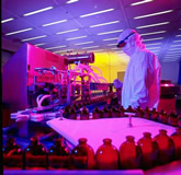
The cleanroom sanitization process requires full sterile gowning and all of the required aseptic techniques that would be utilized during the aseptic filling. As with the aseptic filling process, the cleanroom sanitization process requires documentation, personnel training and qualification. Environmental Monitoring (EM) is the process to ensure that the cleanroom is under control for potential viable and non-viable contamination. Your EM process should have qualified methodologies to routinely collect, evaluate and interpret EM data. The determination of sampling points and required limits should be defined in your documentation. Your EM program should identify periods of critical activity where sterile product may be exposed to environmental conditions (photo Em class 100 Bio Safety Hood).
Sterile Product Filtration
Your drug will require sterilization by some method prior to the aseptic filling process. Traditionally, the bulk drug sterilization is accomplished by filtration, normally a depth filter. You will need to bulk drug a method for sterilization and a sterile container system that is compatible with the drug and your aseptic fill/finish process. The drugs can be pre-sterile filtered (e.g. .45 micron), followed by a series of at least two sterile filters at .22 micron. The sterile filters are both pre- and post-bubble tested to ensure integrity. The Sterile bulk is then transferred to the aseptic fill and aseptically connected to the fill equipment. Currently the best-in-class for sterile filtration is a closed system that extends from the non-sterile bulk to the aseptic filling equipment.
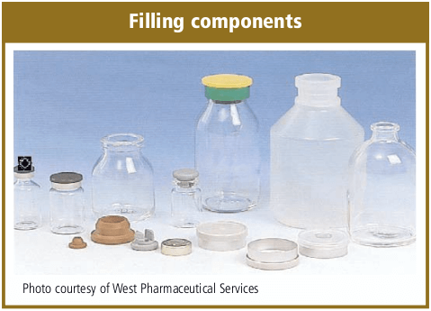
Filling Components
All components and supplies that are required during the aseptic fill/finish operation must be either sterilized or sanitized. Sterilization is usually completed with pass-through steam autoclaves, dry-heat oven or tunnel and sanitized cleanroom airlocks.
The filling components can also vary per the drug and production requirements. Tubular Type I glass vials are predominately used for Small Volume Parenterals (SVP) and sterile lyophilization and blown Type II glass bottles for Large Volume Parenterals (LVP). Tubular Type I glass stock is also predominately used for aseptic syringe production. A number of manufacturers are considering Cyclic Olefin Copolymer (COC) vials that function similar to glass vials.
The stoppering of the vial provides the sterile seal of the drug from the environment and a crimp-seal cap ensures the long term integrity. The stopper also provides a barrier to gas and oxygen to the drug ensuring long term stability. Elastomeric closures (stoppers) that are used for parenteral solutions are formulated to ensure product stability and patient functionality. Two of the basic styles of closures are the “plug” for sterile solutions and the “leg” for sterile lyophilization (clinical solution fill photo). Some of the considerations should be given to size, type and number of needle punctures, water vapor transmission rate, ability to retain bound water, gas transmission, stoppering equipment of the filling line and potential extractables.
Component Preparation
There are many ways to aseptically fill/finish sterile drugs, which includes the traditional solution filling of glass vials and syringes, sterile powder fills, sterile lyophilization, and blow-fill-seal. For this article, I will only be addressing solution filling and sterile lyophilization. There are many considerations in the selection of your aseptic filling equipment. To name but a few: solution volume, fill tolerance, production throughput, drug viscosity, drug foaming, gas blanketing, drug temperature, potent compounds, drug stability and reactivity.
Sterile preparation of the vials and bottles is achieved by rinsing (washing) to remove endotoxins. The glass vials and bottles are depyrogenation usually with hot air. This is accomplished in a batch mode with an oven, or a continuous process with a tunnel that connects the bottle washer to the filling station.
For small parts cleaning, such as filling needles, forceps and stoppering equipment, as well as stoppers, you will complete the initial washing/rinsing to remove endotoxins and loose particulate. Then wrap the parts for subsequent steam autoclave processing to destroy the endotoxins. Depending on the formulation, the stoppers may be able to be sterilized by irradiation.
Aseptic fill/finish processes can very from a clinical hand fill, to semi-automated mono-block, to a high speed filling lines. Filling equipment systems can be characterized as either “Open,” “Barrier,” “Isolator” and “RABS.”
Filling lines are characterized as having no barriers or other physical restrictions between the sterile operator and the sterile drugs. As a result of EU regulation, open fill lines are not common to commercial aseptic operation, but can be found in Phase I and II clinical manufacturing operations. The barrier filling lines have transparent panels that restrict sterile operator access to the sterile drug. Some of the barrier panels may be designed as doors to the Barrier with very specific operational procedures that support aseptic techniques for use during aseptic fill/finish production.
The solution filling process will include the transport of sterilized vials and bottles, orientation to the filling station, a means for check weighing, stoppering and crimping stations. For high speed lines, there will also be accumulation tables and vial load/loading stations. The filling equipment can include the sophistication of in-line check weigher, automated vision systems, reject stations, and SCADA information systems networked from each equipment’s PLC.
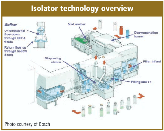
As a rule of thumb, the stoppering and capping (sealing) should be completed as soon as possible. There is some discussion that the crimping of the cap may not require the same critical environment as the solution filling process and crimping may be a particulate generating process. The norm for solution filling equipment is to provide a barrier between the stoppering and capping processes. Isolator systems are a current alternative to the classic barrier equipment installation. Isolators utilize a glove box technology and they are designed for minimal human intervention which provides increased contamination control. A majority of the isolators are sanitized by vaporized hydrogen peroxide. Isolators require more expensive capital investment, can be more complex to install, qualify and operate and may have less flexibility to changeover fill sizes and products. They have historically been designed for high-volume dedicated drug production and microbiological quality laboratory operations. There is also a trend to utilize Campaigning for Isolators technology installations [16].
An alternative to isolator technology is the “Restricted Access Barrier System” (RABS) a term first described by Upjohn, now Pfizer. RABS is similar to the isolator technology utilizing glove ports and other sterile operator restrictions. It is also similar to the traditional barrier fill line with the utilization of a conventional aseptic core cleanroom. The gowning and aseptic techniques are the same as a barrier fill/finish operation. The advantages that have been reported are reduced capital investment, quicker validations and operational start-up, reduction in lot-to-lot turn around time. RABS operations have documented contamination control over a traditional barrier fill/finish system.
Sterile Lyophilization
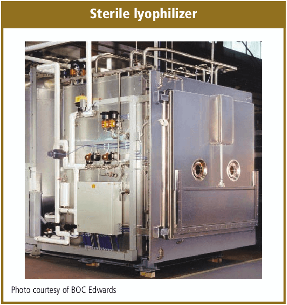
A sterile lyophilization process requires all of the basics for aseptic processing of a solution product, but with the additional processing requirements and risks of the sterile dryer (Lyo) equipment. Sterile dryers are now designed to utilize Clean-in-Place (CIP) and Sterilization-in-Place (SIP) of both the condenser and the product chamber.
The chamber which holds the drug product being processed requires a loading methodology that is consistent with aseptic techniques. For high production and large sterile dryers, the majority of new installations also include automated load and unload equipment. The automated load/unload capability reduces the headcount inside the aseptic core and should reduce the risk to microbial contamination.
The lyophilization process includes filling the product solution aseptically, with the stopper partially seated in the vial. The partially stoppered vial is then transported and loaded into the sterile dryer, thus the sterile product has an extended exposure to the environment. The drug solution is then frozen by either immersion in liquid nitrogen prior to loading or by the sterile shelf. The lyophilization cycle includes the primary and secondary (terminal) drying. After the lyophilization cycle has been completed, the stoppers are usually seated into the vial by lowering the dryer shelves. A sterile drug producer may need to stopper the lyophilized vials under vacuum or and inert gas. Then the dryer door is opened and the stoppered vials are transported to a capping (crimping) process.
Media fills for process validation for a sterile dryer is not a full process simulation. The lyophilization process is usually conducted under near vacuum, with a slight amount of pressure provided by sterile nitrogen and at -35°C or colder. All three of these variables have a negative effect on media and will distort the results. Thus, most companies will modify the media fill in the sterile dryer by not freezing the shelves, not evacuating the chamber and connecting sterile air to the chamber inlet.
Visual Packaging Inspection
Visual packaging inspection of aseptic filled drugs is usually completed 14 days after fill. This is a period of time that could allow the growth of any potential contaminating micro organisms. The critical inspection process is for the presence of a cloudy or hazy solution that would indicate a contamination potential. The manual version of this inspection occurs with the use of white and black background viewing areas.
Manual visual inspection requires trained and tested inspectors, and due to the repetition of the inspection task, it is really only about 85% effective. Thus a number of companies have implemented double- inspection of the product, very tight acceptance criteria and automation of the process with vision systems.
Appendix
- Guideline on Sterile Drug Products Produced by Aseptic Processes, FDA, pub. 1987.
- Guidance for Submitting Documentation for Sterilization Process Validation in applications for Human and Veterinary Drug Products, FDA, pub. 1993.
- ISO 13408-1 Aseptic Processing of Health Care Products.
- ISO 14644 Cleanroom Standard (replaces MIL-STD 209E, obsolete 2001).
- Annex 1, Manufacturer of Sterile Medicinal Products, Pharmaceutical Inspection Convention, pub. 2003.
- USP <61> Microbial Limits.
- USP <1116> Cleanrooms.
- Validation of Aseptic Filling for Solution Drug Products, PDA Technical Monogram, Number 2, pub. 1981.
- Process Simulation Testing for Aseptically Filled Products, PDA Technical Report Number 22, pub. 1996.
- Points to Consider for Aseptic Processing, PDA, pub. 2003.
- Current practices in the Validation of Aseptic Processing, PDA Technical Report Number 36, pub. 2002.
- Design & Validation of Isolator Systems for the Manufacturer and Testing of Health Care Products, PDA, Technical Report Number 34, pub. 2001.
- Aseptic Pharmaceutical Manufacturing, published 1987 by Interpharm Press.
- ISPE Baseline Pharmaceutical Engineering Guide, Volume 3, Sterile Manufacturing Facilities, Jan. 1999.
- FDA Concept Paper on Aseptic Processing: www.fda.gov/cder/dmpq/aseptic-cp.pdf
- D. Stockdale, “Isolator Campaigning – An Industry Survey & Discussion of Operational Practices ”, published by ISPE Pharmaceutical Engineering Magazine, 2004.
Table 1. Definition of Terms for Aseptic ProcessingBasic terms defined
(source: ISPE Definition of terms) |
Table 2. Basic Aseptic Cleanroom Gowning
Note: Gowning in Critical area (Class 100/Grade A) becomes more stringent when working with exposed sterile drugs.Operators should gown with additional sterile sleeves, sterile glove changes, & sanitize of gloves. |
Table 3. Cleanroom cIassification examples |
|
| FDA categories | EU annex 1: 4 categories (A-D) |
| Class 100 | GradeA (Critical 100) |
| Class 1,000 (optional) | Grade B (Aseptic 100 non-unidirectional) |
| Class 10,000 | Grade C (Controlled l0,000) |
| Class 100,000 | Grade D (l00,000) |
| Douglas Stockdale is the President of Stockdale Associates, Inc., which provides extensive aseptic fill/finish and sterile packaging consulting services for the life sciences industry. He had twenty years of operational experience with Baxter Healthcare prior to founding Stockdale Associates. He is an internationally known expert consultant, speaken and writer about the issues of aseptic fill/finish and sterile packaging. His company provides innovative strategic and implementation solutions for product development, manufacturing, compliance/auditing and validation. He is a member of PDA, AAPS IOPP & ISPE and a member ofthe Board of Directors for the Greater Los Angeles chapter of ISPE. Mr Stockdale has a MBA jrom University of La Warne and B.S. in Engineering from Michigan State University. |
| Contacting the author: Douglas Stockdale, President, Stockdale Associates, Inc. Corporate Offices: 10 Reata, Rancho Santa Margarita, CA 92688, Phone: 949-888-9488, Fax: 949-888-1560 douglas@stockdale-inc.com or wwwstockdale-inc.com |
This article was printed in the September/October 2004 issue of American Pharmaceutical Review. Copyright rests with the publisher. For more information about APR and to read similar articles, visit www.americanpharmaceuticalreview.com and subscribe for free.
The post Overview of Aseptic Fill/Finish Manufacturing appeared first on BioRealty, Inc..
Designing a Flexible Facility for Biopharmaceuticals 12 Jun 2015, 9:29 am
By incorporating flexible design features in initial facility construction, biotechnology companies can move from pilot to production operations and market entry in a timely and cost-effective manner. This article describes a 30,000 ft2 facility designed to accommodate phase 1, 2, and 3 clinical trials.
The number of biologics approved for therapeutic applications and clinical trials is increasing. Early in 1992, the Pharmaceutical Manufacturers Association reported that 14 biopharmaceuticals were in development, with 58 companies involved in effort (1). By the end of 1992, FDA approved six more biologics – four therapeutics and two vaccines (2).
Of the many biologics in development and clinical trials, only a few will successfully reach commercialization. Most biologics are produced by either by cell culture (mammalian and insect) or microbial culture (bacterial and yeast). Facilities involved in producing biologics for clinical trial and final market entry must comply with a number of government regulations and conform to numerous “Guidelines” and “Points to Consider” documents issued by the Food and Drug Administration (FDA) (3-12).
Critical elements of regulations that apply to biopharmaceutical facilities have been previously reviewed (13-16). The volume of regulations, together with the complexities of the production technology involved, dictates that the construction and validation of biological production facilities is not a trivial financial or technical undertaking.
To Build or Rebuild?
Initially, for most biotechnology and pharmaceutical companies, a key decision is whether to build a new facility or to remodel an existing building. The next decision is whether to limit the operation of the proposed facility to pilot operation for phase 1 and 2 clinical trials or to build a facility capable of producing material for phase 3 clinical trials and market entry.
Frequently, it is more convenient and cost-effective to build a new facility than to renovate an existing building to function as a pilot facility (17). But in some circumstances this may not be the case. If the decision is to renovate an existing facility, attention should focus on separation of services (such as autoclave, water system, HVAC. and depyrogenation oven), raw material, product, and personnel flow from nearby research operations. If a facility’s scope includes eventual expansion for phase 3 clinical trials and early market production, the pilot facility should have the flexibility and elements to allow this. This adds to the initial cost of the facility but reduces unnecessary time loss that would occur if a new production facility were built after phase 2 clinical trials.
In this article we discuss design and operation of a 30,000i-ft2 research and pilot facility capable of producing biologics for phase 1,2, and 3 clinical trials and early market entry. This facility was built in an open space adjacent to existing research laboratories and office space. Its main function is to produce bulk, purified murine and chimeric motioclonal antibodies (Mabs) derived from cell culture and Mab fragments (Fab, Fv) derived from microbial culture. The antibody products produced in the facility are intended for radioimmunoconjugate MAb cancer therapy.
General Layout
Figure 1 illustrates the general layout of the facility. Administration, research areas, and quality control (QC) labs were already present in the facility. and the rest of the building was retrofitted to function as a pilot and production facility to produce biologics. The facility was sized to produce kilogram quantities of biologics derived from cell culture and microbial sources for all phases of clinical trials and early market entry.
A linear, unidirectional flow of operations is preferable. But in this case, structural constraints necessitated a circular unidirectional flow for the cell culture facility to prevent the mixup of clean and used equipment and glassware. The microbial facility is physically separated from the cell culture facility with its own dedicated single-pass heat ventilation and air-conditioning (HVAC) system. Furthermore, entry to the research area is separate from the production area (RE and PE, in Figure l).
The research area consists of three 600-ft2 molecular biology laboratories where chimeric, humanized, bacterial- and yeast-derived antibody and antibody fragment-secreting clones are engineered. The cell culture research and process development laboratory is located in this area, Cell culture process development uses five 2-L bioreactors and one 40-L bioreactor. Cell culture is generally performed under antibiotic-free conditions.
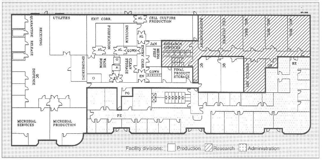
Figure 1. General facility layout for a flexible, biopharmaceutical pilot facility with a 30,000-ft2 area. AL = airlock; EN = entry airlock; EX = exit airlock;O = GMP depyrogenation oven; A = GMP autoclave; Utilities = UHQ water, pure steam, plant steam; Entry Corr = entry corridor to cell culture facility; Exit Corr = exit corridor from cell culture facility; QC = quality control; Mol Biol = molecular biology laboratory; RE = research laboratory entry/exit; PE = production facility entry/exit; PG = pregowning room; Jan = janitorial supply room; DR = dark room; PG = pregown room.
To minimize contamination, cell culture research and cell culture process development laboratories are equipped with Cleanroom washable ceiling tiles and ceiling HEPA-filtered air that reduces particulate (0.2- and 0.5-μm) count of 100,000-300,000 by 10- to 30-fold. The research laboratories are serviced by a single-pass HVAC system and have a slight negative pressure with respect to the corridor. This reduces cross contamination between different laboratories. The research area has its own dedicated autoclave, reverse-osmosis and deionized (RO/DI) water system, depyrogenation oven, dishwashers. and dryers (Figure 1).
Cell and Microbial Production
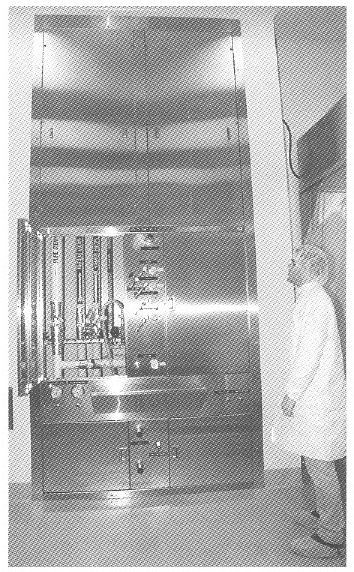
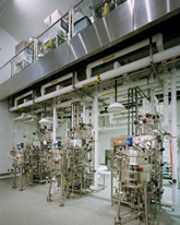
Figure 2. View of a general purpose service panel providing air. nitrogen, oxygen, and carbon dioxide services to bioreactors and process equipment.
The cell culture facility comprises a gown room, a wash room. a clean storage area, a medium preparation area, an inoculum preparation area. a cell culture production area. an entry and exit corridor, and associated airlocks (Figure I). The cell culture production area is a 1250-ft2 with a 14- foot hard ceiling to accommodate a variety of bioreactors and process equipment, The cell culture production area is isolated from the rest of the facility by two airlocks that are pressurized in both directions (EX and EX, Figure 1). To enter cell culture facility production, personnel must pregown (PG, Figure 1), and after passing through the cell culture facility airlock (EN) they must gown in a EPA-filtered gowning room (supplied with terminally HEPA-filtered air at 250 changes per hour). In this gowning room, the large volume of laminar airflow substantially reduces introduction of particulate matter by personnel. Exit from the cell culture facility is through an exit-only corridor, through the wash area, through the exit airlock, and out of the facility(EX).
Utility panels. Three utility panels (Figure 2) can service three bioreactor skids or other process equipment in the cell culture production area. Each utility panel was designed to provide flexibility to operate any type of bioreactor: hollow-fiber, stirred-tank, airlift, and other process equipment. Each utility panel is equipped with the following services: pure steam, gasses (air, oxygen, nitrogen, and carbon dioxide). A vent for bioreactor exhaust gases. capped drain, chilled water, potable water, ultra high quality (UHQ) water, and 110- and 208-V electricity. Because of continuous improvements in cell culture methodology and the need to grow either suspension or anchorage-dependent cells. flexibility is essential in the design of a cell culture pilot and production facility. Inoculum seed cultures are prepared in the inoculum reparation room. and purification and simple chemical modification of proteins are performed in the purification area (Figure 1). Cell culture production and purification are isolated by their respective airlocks. Purification has a secondary gowning room. Media are prepared in the medium preparation room in 15- 500-L medium preparation vessels. Process equipment is washed, steam sterilized, autoclaved, and depyrogenated in the wash room and stored in the clean storage room (Figure 1).
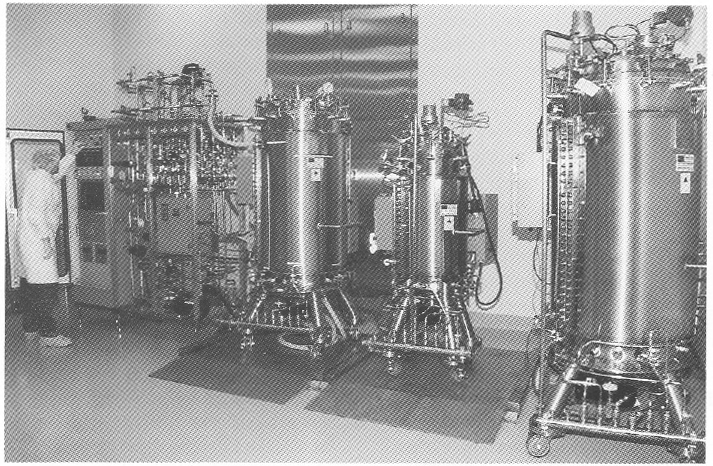
Bioreactor. A unique bioreactor (Figure 3) was designed to service the flexible requirements of large-scale cell culture of mammalian and insect cells. The bioreactor consists of one 100-L vessel and three 400-L working volume vessels. This system is capable of 100- and 400-L batch culture in airlift. stirred. or airlift-stirred combination mode. This is possible because of the flexible design of the bioreactor, in which draft tubes, baffles. or impellers can be added or removed from the bioreactor vessel. Semicontinuous culture can produce 50-200 L of tissue culture harvest per day. The 100- and 400-L vessel can also be perfused with fresh media while cells are retained within the bioreactor during perfusion culture. This results in 150-600 L of high cell density, 5-15 million cells/mL of cell culture harvest. Microcarrier culture in 100- and 400-L/batch or 150-600 L/day perfusion mode can also be performed by the bioreactor, The cell culture production area can accommodate three such bioreactors.
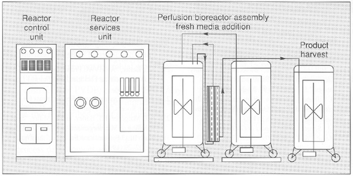
Figure 3. An “all in one” bioreactor with three 500-L tanks and one 100-L. tank (above and below). The diagram (above) depicts a perfusion assembly in which cells growing in a 400-L vessel are recirculated through a hollow-fiber back to the bioreactor while the product is harvested in the product harvest tank. Fresh media is added to the bioreactor by a third tank. Each vessel is equipped with a removable draft tube and an impeller with an adjustable height on the agitator shaft.
Both in-process and final bulk products are stored in final product storage (Figure 1) where they are released for further processing after appropriate quality control (QC) testing.
The microbial production area (Figure 1) is equipped with separate dishwashing and autoclave services. This area can accommodate a 100- and 1,000-L working volume bioreactor operating in batch mode.
Purification area. A number of large-scale processes are available to purify secreted or nonsecreted biologics from microbial and cell sources (18), Bulk, cell-free, concentrated harvest from cell culture and microbial production (microfiltered and ultrafiltered) is purified in the purification area (Figure 1). Low-, medium-, and high- pressure liquid chromatography can be used to produce kilogram quantities of bulk biologic in the purification area. Temperature control is provided by either HEPA-filtered refrigerators or temperature controlled jacketed buffer tanks and columns. Bulk biologic produced from cell culture and microbial sources is stored in final product storage and. after QC release, is vialed in a separate facility.
One product at a time is processed in either the cell culture or microbial production area and then processed in the purification area to prevent mixing of the product with raw or in-process material. The facility is completely cleaned after each product campaign. Facility access areas are cleaned daily, and the entire facility is cleaned weekly from ceiling to floor. Cleaning detergents are rotated biweekly.
Cell culture and purification waste is chemically decontaminated, and pH is neutralized using a 500-L working volume chemical kill system. Microbial waste is heat inactivated before disposal. Production and research areas are serviced by a separate drain system.
Utilities and Services
Utilities for production operations are located in the utility area (Figure 1). A 2,000-lb/hour plant steam boiler provides raw steam with no chemical additives for pure steam generation from UHQ water (located adjacent to the plant steam boiler) and also provides humidity for HVAC and waste autoclave located in the washroom. A 1,000-lb/hour pure steam generator provides pure steam for bioreactor sterilization and GMP autoclave chamber and jacket.
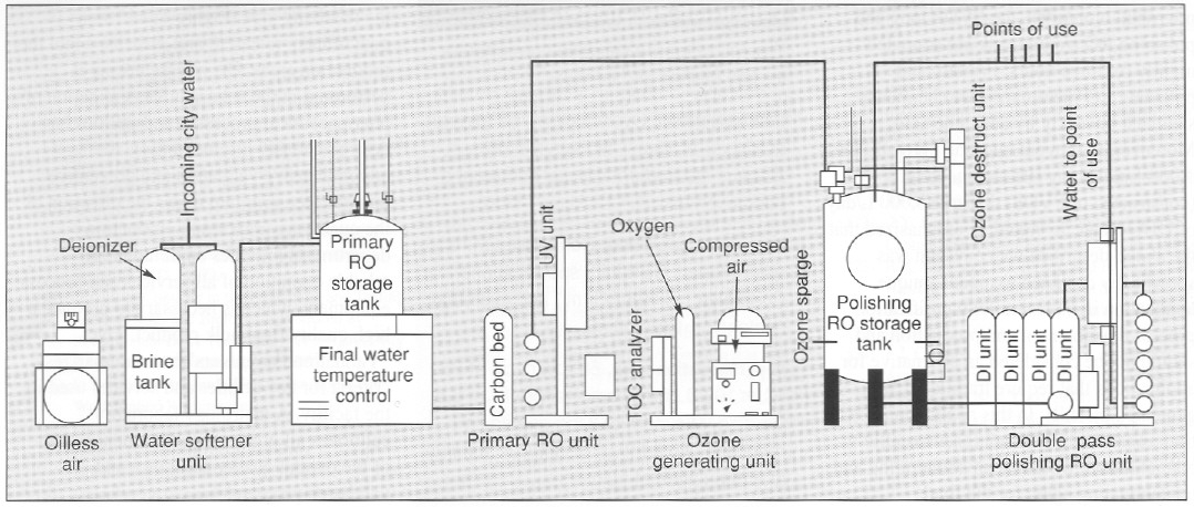
Figure 4. View and diagram (above and below) of a 13-gpm UHO water system providing 18-megohm metal-tree water with, 10 ppb of total metal content. This meets and exceeds WFI specification for the production of protein-chelator complexes tor radioimmunoconjugate application.
Depyrogenation. Pyrogens from bacterial residues can be a major contaminant of process equipment. A number of methods are available to remove pyrogens (19). A double-door depyrogenation oven (O, Figure 1) with a 30-ft3 chamber depyrogenates heat-resistant glass and stainless steel components at 250 °C. A double door GMP autoclave (A, Figure 1) with a 60-ft3 chamber provides autoclaving services. The microbial facility is equipped with a separate 15-ft3 autoclave and dishwashing services.
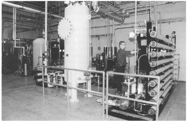
Special water requirements. The product being produced in this facility is an antibody conjugated to an organic chelator that binds a radioisotope (90 Yttrium). The final product is an unbound antibody conjugate for which chelation to the radioisotope 90Y is performed at the hospital. For this class of products, very low concentrations (less than 10 ppb or μg/L) of total metal are necessary for water used for final product purification and processing. Metal contaminants from traditional stainless steel, multiple-effect, and vapor compression water for injection (WFI) systems will bind the chelate and adulterate the final product (20). Traditional WFI distribution systems where water is recirculated in an 80 °C stainless steel hot loop cannot reliably produce water with the required low total-metal content. To address the special water requirements. a unique 13-gpm, continuous-flow. three-pass reverse-osmosis (RO) water system (Figure 4) was designed to produce pharmaceutical-grade UHQ water suitable for final product processing.
To guarantee high water quality, a storage tank is located in front of the final double-pass polishing RO membranes. Water is directly circulated to points of use from the polishing RO membranes at a rate of 13 gal/min (approximately 75,000 L/day). The quality of water used in this process is similar to type E-l water produced for use in the electronics industry and is of much higher purity in terms of metal, organic, endotoxin. and microbial contaminants when compared with water from traditional pharmaceutical- grade stills.
Water recirculates in a piping loop constructed of polyvinilidine difluoride (PVDF). To maintain low endotoxin and microbial bioburden, the PVDF loop and polishing RO storage tank are ozoneted nightly for three hours. Primary and polishing RO membranes are chemically sanitized biweekly by peracetic acid. Moreover, to prevent microbial growth. The 1,000-L polishing RO storage tank (constructed of PVDF) discards 8,000 L/day of UHQ water. It should be emphasized that the above-described water system was specifically designed to meet at unique application in biotechnology purification process development and production and should not be considered an alternative for applications that require traditional WFI, generated by stills. In this application, traditional WFI, with its higher metallic contaminants, would be an adulterating and contaminating agent for the final immunoconjugate products.
HVAC units. Special considerations determine the design of HVAC systems for biologics pilot production facilities (21, 22). Separation of HVAC units is necessary for critical processes to prevent cross-contamination of air. In the facility discussed here. the cell culture inoculum area, cell culture production urea, and associated airlocks are serviced by one HVAC unit. The purification area and its associated airlocks are serviced by another HVAC unit. Air entry into each room is terminally HEPA-filtered at the ceiling with 25 air changes in the cell culture inoculum and cell culture production areas and 50 air changes in the purification area. As currently configured, air is recirculated at a rate of 80% in the above areas and meets the requirements of biosafety level 1 (BL-1); however, the HVAC system can be modified to generate single-pass air for biohazard process applications and applications higher than BL-1.
| VALIDATION PARAMETERS |
| The following are validation parameters for key utilities and services |
| GMP autoclaves. Overkill cycle, 60 minutes at 121°C at 15 psi. No survival of Bacillus stearothermophilus spores at a population of 106 |
| Pure steam generator. Condensed pure steam meets USP WFI specifications. Endotoxin <0.125 EU/ml, and microbial content <1 Cfu/100 mL. |
| Depyrogenation oven. 60 min. cycle at 250°C. <100 0.5 μm particles/ per ft3 of 0.5 μm size. Minimum of 3 log endotoxin reduction. No survival of Bacillus subtilus at a population of 106. |
| Ultra high quality water. <10 ppb of metals (such as Ni, Cu, and CO), <10 PPB of organics; <0.03 EU/mL of endotoxin; and <1Cfu/100mL. Resistivity 15-18 megohm. Meets and exceeds USP specifications for water for injection (WFI). |
| HVAC and environmental baseline. Controlled areas except wash and microbial production (10,000 particles/ft3/min) and wash room and microbial production (100,000 particles/ft3/min). < 25 viable organisms/10 ft3 of air; temperature 23±3°C; and humidity 40-60%. |
A dynamic particulate count of < 10,000 is maintained in both the production and purification areas. Counts of < 1,000 are typical during operation. Airlocks adjacent to the facility are all at positive pressure (with respect to both the facility and its exterior) to prevent particulates from either entering or exiting the facility.
A third HVAC unit services the media preparation and clean storage areas and the clean corridor where air passes once from the clean areas and exits into the exit corridor and the wash room. The particulate count in the clean storage and media preparation areas and the entry corridor is maintained at a particle count of < 10,000 during active periods. The particulate counts in both the exit corridor and the wash room are maintained at < 100,000 during active periods. Because large-scale production of biohazardous microorganisms requires both single-pass air and at backup HVAC, a fourth HVAC backup unit can be used if there is a need to comply with HVAC requirements of large-scale BL-2 (23). Currently, the facility operates at BL-1 level. All processes are performed in closed vessels (production, microfiltration, ultrafiltration, and purification), and large process vessels are isolated from the environment by 0.2-μm filters.
The microbial production area is serviced by one centrally HEPA-filtered, single-pass HVAC that provides a production area with a particle count of <100,000.
Validation. Raw materials are delivered to the receiving area (Figure 1] and then quarantined, released, and dispensed into the production areas. QC release testing is performed in QC laboratories. Validation of pharmaceutical processes and utilities has been previously discussed (24). A comprehensive validation and preventive maintenance program under the direction of the quality assurance and production departments provides continuous and reliable operation of all services and process equipment, which is necessary to produce a high quality final bulk product. The “Validation PARAMETERS” box summarizes criteria for key utilities and services used in the facility. A metrology laboratory calibrates all processing equipment as part of the overall quality assurance and validation program.
Because all biologics are thermolabile, terminal sterilization cannot be used to produce sterile bulk product, Instead, aseptic filtration is used before vialing. Stability of the cell lines (measured by specific activity and specific productivity of cell line), in-process product, and final bulk stage is assessed mainly by physiochemical protein analytical techniques (25). Final product is vialed under liquid or lyophilized conditions in at separate dedicated facility.
Maximizing Flexibility
The flexible pilot-production facility described here is capable of producing gram to kilogram quantities of biologics for research. All phases of clinical trials. And early market entry. Key features of the present facility are its flexibility in handling a variety of cell culture processes and bioreactors; a novel bioreactor system that can operate in a number of modes to meet the diverse needs of cell culture production processes; and a unique UHQ water system with 10-ppb metal concentration.
These design features will assist new biotechnology operations in designing flexible operations lo meet their internal research. clinical, and market-entry requirements, all while minimizing cost and maximizing flexibility. speed, and efficiency.
References
(1) In Development Biotechnology Medicines (Pharmacetical Manufacturers Association, Washington, D.C., 1992)
(2) T.L.Copmann, “FDA Approves 6 Biologic Therapeutics and Vaccines, “New Drug Approvals in 1992 (Pharmaceutical Manufacturers Association, Washington, D.C., 1993), pp. 5-6
(3) Code of Federal Regulations, Title 21, Parts 600-680 (U.S. Government Printing Office, Washington, D. C. 1992).
(4) Code of Federal Regulations, Title 21, Parts 200-211 (U.S. Government Printing Office, Washington, D.C. 1992).
(5) “Points to Consider in the Characterization of Cell lines Used to Produce Biologicals” (Food and Drug Administration, Bethesda, MD, 1987).
(6) “Points to Consider in the Manufacture and Testing of Monoclonal Antibody Products for Human Use” (Food and Drug Administration, Bethesda, MD, 1987).
(7) “Points to Consider in the Manufacture and Testing of New Drugs and Biologicals Produced by Recombinant DNA Technology” (Food and Drug Administration, Bethesda, MD, 1985).
(8) U.S. Federal Standard 209D, Clean Room and Work Station Requirements.
(9) Guideline on Sterile Drug Pruducts Produced by Aseptic Processing (Food and Drug Administration, Bethesda, MD, 1987).
(10) Guideline on General Principles of Process Validation (Food and Drug Administration, Bethesda, MD, 1987).
(11) Proposed GMP for Large Volume Parenterals, 21 CFR, section 212, 1976.
(12) US. Dept. of Health and Human Services, Biosafety in Microbiological and Biomedical Laboratories, (U.S. Government Printing Office, Washington, D.C., 1984).
(13) D. Hill and M. Beatrice , “Biotechnology Facility Requirements, Part 1, Facility and Systems Design,” BioPharm 2 (9), 20-26 (1989).
(14) D. Hill and M. Beatrice , “Biotechnology Facility Requirements, Part 2, Operating Procedures and Validation,” BioPharm 2 (10), 28-32 (1989).
(15) P.L. Simmons, The Impact of GMPs on the Manufacture of Bulk Pharmaceticals Chemicals/Biologics (ICT2, Miami, FL., 1988).
(16) P.L. Simmons, The Design, Construction and Commissioning of a New Facility in Accordance with GMP Regulations (ICT2, Miami, FL., 1988).
(17) D. Robin and R. Del Ciello, “To Renovate or Build New; Guidelines for Evaluation Construction Alternatives,” BioPharm 1 (1), 34-38 (1988).
(18) R.J. Giorgio, “Facilities for Large-Scale Protein Purification and Isolation,” BioPharm 1 (5), 38-46 (1988).
(19) M. Weary and F. Pearson III, “A Manufacturer’s Guide to Depyrogenation,” BioPharm 1 (4), 22-29 (1988).
(20) E.E. Bjurstrom and D. Coleman, “Water Systems for Biotechnology Facilities,” BioPharm 1 (0), 50-55 (1987).
(21) S.L. Kelter, “An HVAC Primer for Biopharmaceutical Facilities,” BioPharm 1 (5), 30-37 (1988).
(22) J.Y. Lee, “Environmental Requirements for Clean Rooms,” BioPharm 2 (2), 42-45 (1989).
(23) R.Z. Maigetter, F.J. Bailey and B. Miller, “Safe Handling of Microorganisms in Small- and Large-Scale BL-3 Fermentation Facilities,” BioPharm 3 (2), 22-29 (1990).
(24) F.J. Carleton and J.P. Agalloco, Validation of Aseptic Pharmaceutical Processes (Marcel Dekker Inc., New York, 1986).
(25) “Assessment of Genetic Stability for Biotechnology Products,” Pharmaceutical Manufacturers Association 4 (2), 22-27 (1991).
The post Designing a Flexible Facility for Biopharmaceuticals appeared first on BioRealty, Inc..
The Biomedical Industry’s Emerging Clusters 22 May 2015, 9:27 am
Because government agencies, educational institutions, and pharmaceutical companies are becoming increasingly aware of the benefits that attracting biomedical companies to their area represents, a geographic shift is occurring that could alter the landscape when it comes to biomedical “clustering.”
Critical to the success of any biomedical cluster are basic essential support systems including a history of successful commercialization of technologies, an understanding of the unique needs of the biomedical industry, the availability of venture capital for startup and established companies, as well as strong support from the government. Additional key ingredients include access to leading research universities and pharmaceutical companies, an abundance of skilled workers, a growing community of organizations involved in pre-commercial medical research, and the availability of affordable housing to support the organization’s workforce.
In the U.S., where 41 out of 50 states have formal economic initiatives in place that are specifically intended to attract players in the biotech sector or larger biomedical industry, there are only these nine areas which are considered major biomedical clusters today:
· San Diego
· San Francisco
· Seattle
· Los Angeles
· Washington D.C./Baltimore
· Philadelphia
· New York/New Jersey/Connecticut
· Boston
· Raleigh/Durham
However, as economic conditions change, population shifts continue to occur, and these 41 states continue to advance their biomedical initiatives, new economic and lifestyle forces are driving the formation and growth of biomedical clusters. And those drivers are expected to result in new clusters forming in areas not previously under consideration by the industry.
 The biomedical industry is historically known for bringing clean, non-polluting firms that deliver a large quantity of high-paying technical jobs, as well as a number of clerical and administrative jobs, to the communities that are fortunate enough to attract them. It is well known that jobs, especially high paying ones, create a multiplier effect in terms of economic activity for an area. This explains why attracting biomedical firms to a region has become so popular among economic development groups.
In an effort to bring about a change in the current clustering patterns, government agencies, educational institutions, and the private sector are banding together to create and manage biomedical ‘recruitment’ programs that are designed to accentuate the positive features of their geographic area for biomedical companies and compensate for the negative ones.
 A case in point is the recent decision made by Karin Eastham, COO of the Burnham Institute for Medical Research, who relocated her company to Florida after being offered $350 million dollars in medical research funding by Florida’s BioFlorida, an independent association that focuses on recruiting life sciences organizations.[1] In a move designed to leverage the Burnham deal, the University of Florida announced their intention to build a research facility adjacent to the Burnham facility – just like that it appears another biomedical cluster is being born.
Other areas in the U.S. such as Houston, Chicago, Indianapolis, Memphis, St. Louis and Phoenix are making similar efforts to create new biomedical clusters. For example, the State of Arizona has authorized the expenditure of nearly $440 million dollars in grant money to help fund the Biodesign Institute and University of Arizona research facilities.[2]
Part of that funding goes toward the Technology and Research Initiative Fund (TRIF), which is to be split between the three universities in the state. According to Barry Broome, CEO of the Greater Phoenix Economic Council, the goal of this fund is to support university science and technology research that will benefit and grow a knowledge industry in the state.
Chicago has also been making a strong bid to develop its reputation as a research-friendly community thanks to the billions of dollars that have been made available to research organizations by government and private agencies.
Chicago’s Abbott Laboratories, which employs over 72,000 people globally and nearly 2,000 in the city itself, spends nearly $2 billion dollars annually on research.[3] Nearby Baxter International, Inc., which employs close to 52,000 employees globally and 1,000 locally, spends almost $600 million dollars on research,[4] but being research-friendly is not the only attraction for Chicago. In fact, when you compare the overall demographics of Chicago with the requirements necessary to support a life science cluster, you see a very close match.
Downtown Chicago is the host to the Chicago Technology Institute, a 56 acre facility located within the Illinois Medical District. The facility provides complete incubator support to medical research companies including complete infrastructure services, access to nearby university resources, and customized business development services based upon each tenant’s needs. So far, the Institute has helped 25 firms move through the incubator phase and out into the general economy.
Houston is seen as another candidate to become a thriving technology cluster. The Texas Medical Center, a consortium of 42 non–profit and government institutions, has received $2.2 billion in grants in just the past 5 years.[5]
These investments have resulted in the successful creation of over 100 start-up research companies which continue to stimulate Houston’s research economy. If fueled by easier access to venture capital these numerous new companies should virtually guarantee the city’s future as an emerging life science cluster.
 Other regions, including Indianapolis, Kansas City, Memphis, Minneapolis/St. Paul, St. Louis, and Madison all possess the resources and demographics necessary to support cluster development, and putting aside the economic offerings being used to attract the biomedical industry, some industry analysts believe that the emerging interest in Embryonic Stem Cell Research, as well as counter bioterrorism research may be the next big drivers that will help form other new biomedical clusters is regions that are not currently considered to be major players.
Outside the U.S., similar efforts are being made to create new, emerging biomedical clusters. The Doors of Perception Blog,[6] a design and architectural publication, reports on “plans in China for the world’s first urban biomedical hub,” to be located in the crowded Xuhui district of Shanghai. This urban cluster, called the Fenglin Biomedical Centre, intends to bring together life science, medical care services, medical education, business incubation, and medical exhibitions.[7]
In Canada, three of its major cities – Toronto, Vancouver and Montreal – have all made terrific progress in the formation of new biotechnology companies, and the major cities in Europe, which produces 40% of the world’s pharmaceuticals[8], and Japan, which is the 2nd largest health care economy in the world[9], are other key areas to watch.
There is no question that the landscape of biomedical clusters is changing rapidly. No longer is biomedical an industry who’s participants will locate almost exclusively on the east and west coasts of the United States. As more and more regions work to create environments where essential support systems are in place (i.e. availability of venture capital, strong governmental support, successful tech transfer, access to academic centers of excellence and big pharma companies, an abundant skilled workforce, and a growing community of organizations involved in pre-commercial medical research) and where these key ingredients all come together, new biomedical clusters will continue to form and flourish. Is your community one of these emerging biomedical clusters?
[1] St. Petersburg Times: State Builds on Biotech Success, 11/15/06
[2] The Arizona Republic: Funding Arizona Industry is an Ongoing Challenge, 11/17/06
[3] Abbott Labs 2005 Annual Report
[6] www.doorsofperception.com/archives/2006/03/post_3.php Biomedical Downtowns, 3/30/06
[8] Colliers Alchemy Report
The post The Biomedical Industry’s Emerging Clusters appeared first on BioRealty, Inc..